AERCO C-More Controls User Manual
Page 22
C-MORE CONTROL PANEL OPERATION
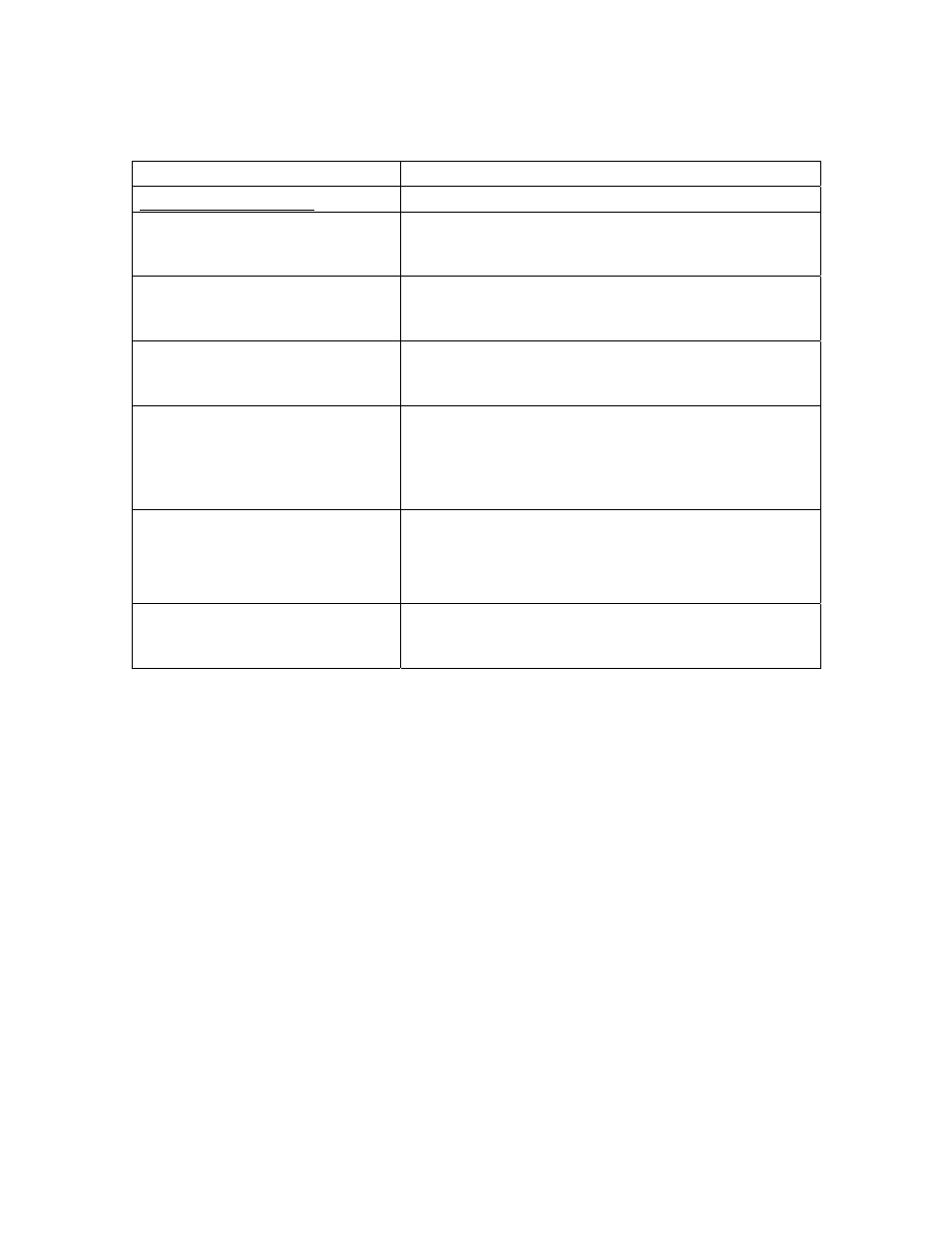
Table 3-1. Menu Item Descriptions – Continued
MENU LEVEL & OPTION
DESCRIPTION
DIAGNOSTICS MENU
Display Test
*
Allows testing of the front panel LED indicators, 3-
character, 7-segment LED display and 20-segment
LED Bargraph.
Keypad Test
*
Allows testing of the operational status of each front
panel key. The VFD will display the name of each
key as it is pressed.
Relay Test
*
Allows user to force relay outputs ON or OFF. The
relays tested include: Igniter, Blower, Pump, Aux and
Fault relay.
Switch Test
*
Allows the ON/OFF status of all switch inputs to be
viewed. These switches include: Exhaust, SSOV,
Blower Proof, Ignition, Over-Temp, Low Gas Pres, Hi
Gas Pres, Water Lev, Rem Int, Front Pnl, Delayed
Int and Purge switches.
Stepper Test
*
Allows adjustment of the Air/Fuel Valve stepper
motor position using the
▲ and ▼ keys. The Bargraph
display will light to indicate the current stepper motor
position.
Sensor Log Int
Allows the Sensor Log Interval to be set to: 1 Min, 5
Min, 15 Min, 30 Min, 1 Hr, 6 Hrs, 12 Hrs or 24 Hrs.
Default setting is 30 Min.
*
Not adjustable via RS232 serial communication
18