38 controls and emergency functions – AERCO Modulex EXT 321 - 1123 User Manual
Page 78
MODULEX EXT 321, 481, 641, 802, 962, 1123 BOILERS
Installation, Operation & Maintenance Manual
3.38 Controls And Emergency Functions
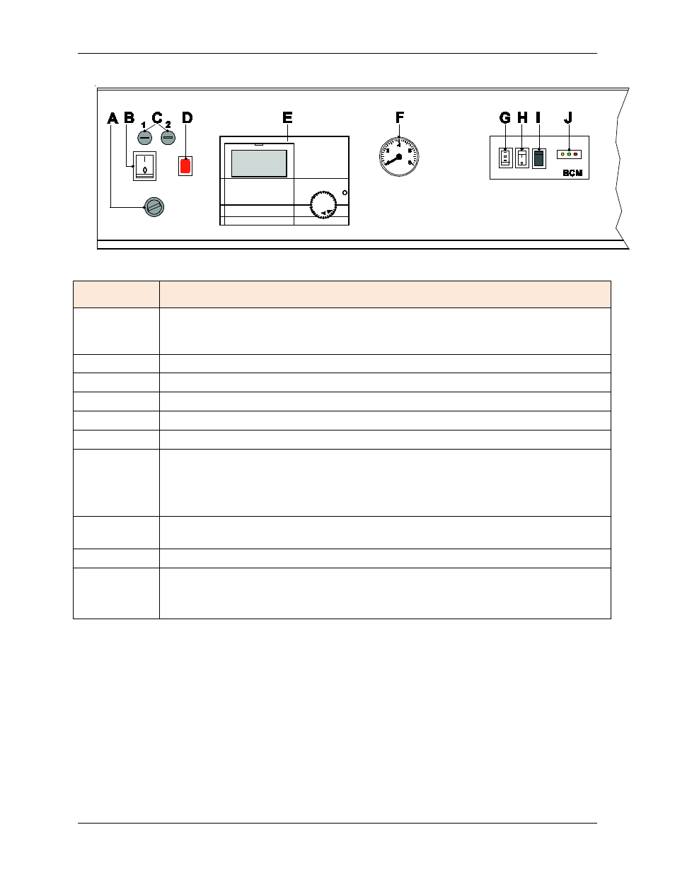
Figure 3-43: MODULEX EXT Panel Controls and Indicators
ITEM
COMPONANT/FUNCTION
A
GLT (General Limit Thermostat): when enabled, it cuts the power supply to the
boiler and lights the warning lamp (Item D). To reset, remove the cap and push
the reset button.
B
Main Power Switch
C
Fuses: 1 = 6.3 A 2 = 10 A
D
Warning lamp of the Thermostatic
Lockout from GTL (General Limit Thermostat).
E
E8 Controller Module
F
Hydrometer (Optional)
G*
Change-over Series/Parallel:
0 = Emergency is active or the control is managed by PLC or BMS.
I = Series connection (the cascade is managed by the BCM)
II = Parallel connection (condition of supply).
H*
In position “I” the plant will operate when requested at “CONSTANT SETPOINT”:
70°C –
Max heat output 50%.
I*
Enables burner reset in case of lock-out.
J*
YELLOW LED = Blinking = Communication between BMM and BCM is OK.
GREEN LED = ON = Active Pump
RED LED = ON = Failure Code Detected
*See section 4.2, below, for more information regarding the BCM (Boiler Communication
Module).
NOTE
The emergency function enables the boiler’s burners to fire only at 50% and at
50°C in system return. All the system’s heating loads, including the header pump,
must be controlled manually.
Page 78 of 148
AERCO International, Inc. • 100 Oritani Dr. • Blauvelt, NY 10913
OMM-0087_0E
12/01/14
Phone: 800-526-0288
GF-143