AERCO Modulex EXT 321 - 1123 User Manual
Page 130
MODULEX EXT 321, 481, 641, 802, 962, 1123 BOILERS
Installation, Operation & Maintenance Manual
Disassembling the Boiler for Maintenance – Continued
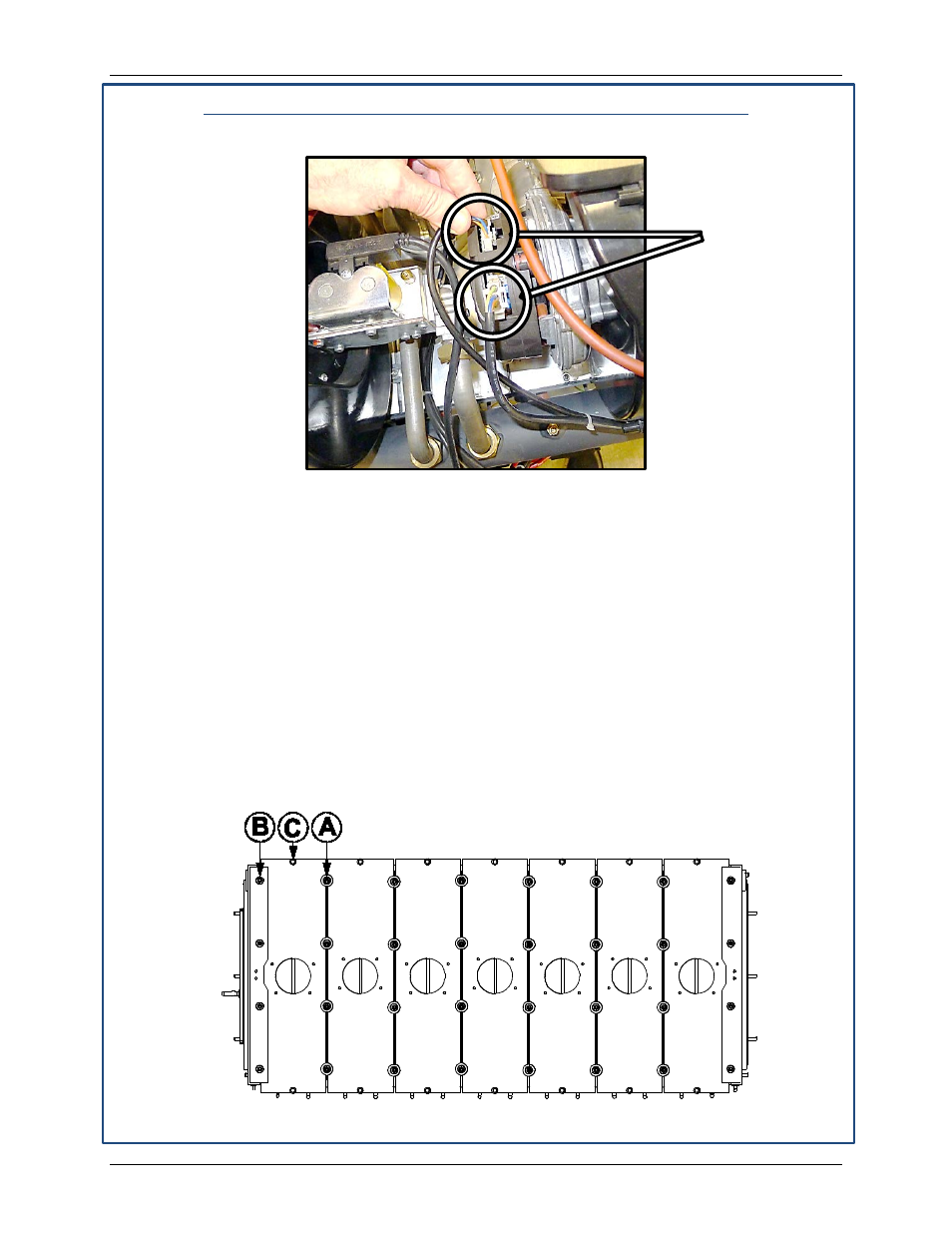
8. On each fan, remove each (of two) Fan Connectors (Figure 4-10)
Figure 7-12: Removing Both Fan Connectors from All Fans (Step 8)
9. Burner maintenance may be performed on all burner modules simultaneously or on each
one separately, as described in a) and b) below:
a) All Modules: Use a 13mm wrench to remove all “A” and “C” nuts (surrounded by
horizontal dotted lines in Figure 7-11, below). Leave the “B” screws affixed so all
burner plates may be lifted together. Then complete the remainder of the instructions
in this section.
b) Separate Modules: Use a 13mm wrench to remove only the “A” and “C” nuts on
either side of the module in question (vertical dotted lines in figure 7-12), then
remove the “B” Phillips screw at the end of the burner module. You can then skip the
remaining steps in this section and continue with section 11 -
Cleaning the Burner
Module and Combustion Chamber.
10. To access individual burner modules, refer to Figures 7-13 and 7-14 and, using a standard
Phillips head screwdriver, remove the “C” screws of each burner module to be accessed.
These are the screws that are located at each end of each burner plate (2 per plate).
Figure 7-13: Removal of Burner Plate Hardware (Steps 9, 10, 11)
Remove Two
Connectors
from Each Fan
Page 130 of 148
AERCO International, Inc. • 100 Oritani Dr. • Blauvelt, NY 10913
OMM-0087_0E
12/01/14
Phone: 800-526-0288
GF-143