AERCO BMK 1000 User Manual
Page 91
Benchmark 750/1000 Boiler Installation, Operation & Maintenance Manual
CHAPTER 7 – MAINTENANCE
OMM-0082_0J
AERCO International, Inc. • 100 Oritani Dr. • Blauvelt, NY 10913
Page 91 of 192
GF-130
Ph.: 800-526-0288
05/21/2014
Igniter-Injector Replacement
–
Continued
3. Disconnect the cable from the igniter-injector (
Figure 7-1
).
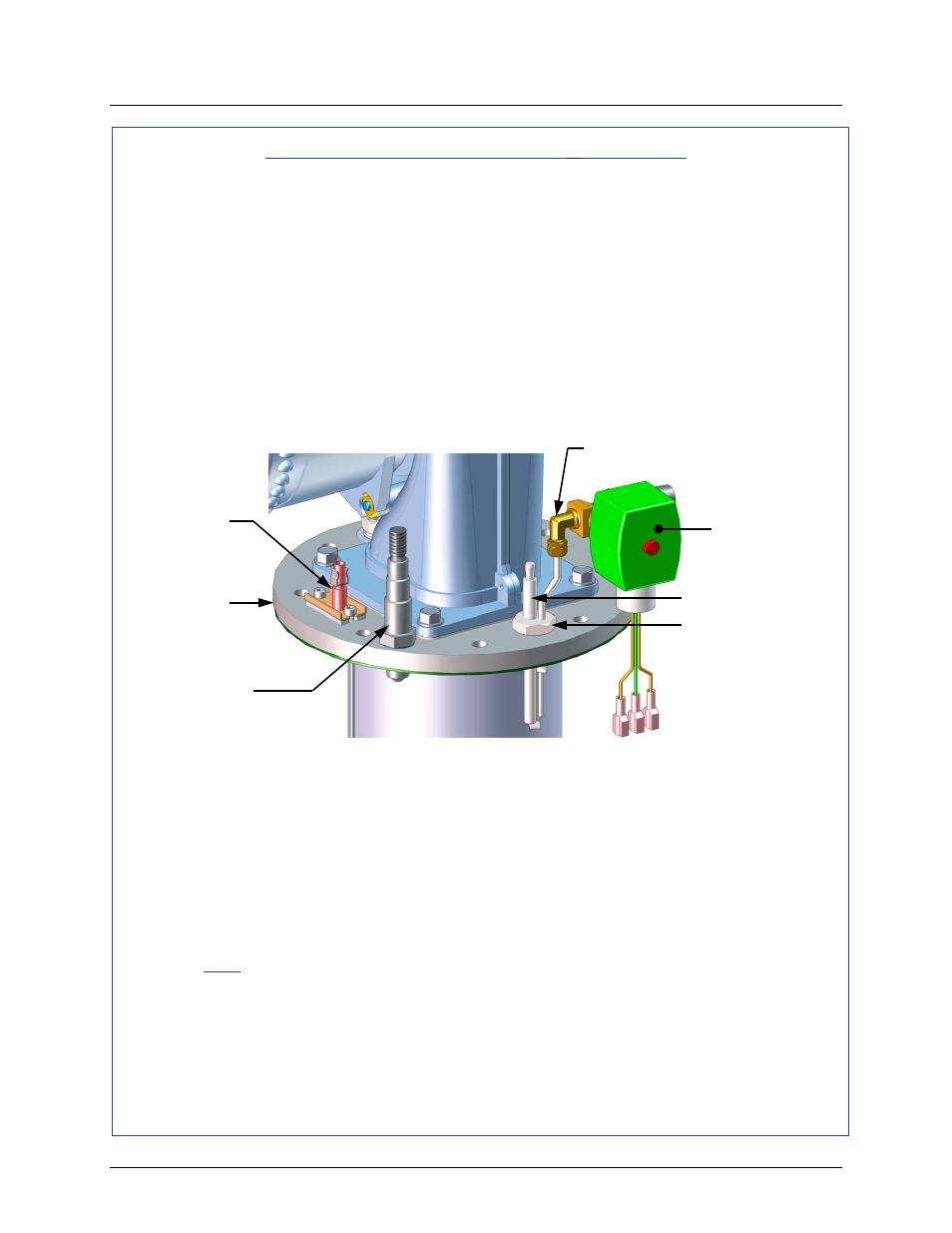
4. Refer to the partial exploded view in Figure 7-2. Using a 7/16” open-end wrench,
disconnect the compression nut securing the gas injector tube of the igniter-injector to the
elbow of the staged ignition assembly. Disconnect the staged ignition assembly from the
igniter-injector.
5. Next, loosen and remove the igniter-injector from the burner plate using a 1" open-end
wrench.
6. Check the igniter-injector for evidence of erosion or carbon build-up. If there is evidence
of substantial erosion or carbon build-up, the igniter-injector should be replaced. If carbon
build-up is present, clean the component using fine emery cloth. Repeated carbon build-
up is an indication that the combustion settings of the unit should be checked. Refer to
Chapter 4 for combustion calibration procedures.
Figure 7-2: Igniter-Injector & Flame Detector Mounting Details
7. Next, loosen and remove the igniter-injector from the burner plate using a 1" open-end
wrench.
8. Check the igniter-injector for evidence of erosion or carbon build-up. If there is evidence
of substantial erosion or carbon build-up, the igniter-injector should be replaced. If carbon
build-up is present, clean the component using fine emery cloth. Repeated carbon build-
up is an indication that the combustion settings of the unit should be checked. Refer to
Chapter 4 for combustion calibration procedures.
9. Prior to reinstalling the igniter-injector, a high temperature, conductive, anti-seize com-
pound must be applied to the threads.
NOTE
If a replacement igniter-injector (part no. 58023) is being installed, a
compression nut containing a built-in ferrule will be included with the
replacement part. If needed, 3 indexing washers are also included These
washers may be needed to properly position the gas injector tube of the
igniter-injector within the 120° angle range shown in Figure 7-3.
O2 SENSOR
& WASHERS
STAGED
IGNITION
SOLENOID
INJECTOR-IGNITOR
INDEXING WASHERS
(Quantity = 0-3 as
required)
FLAME
DETECTOR
& GASKET
COMPRESSION FITTING AND ELBOW
BURNER
PLATE