3 accessing the analyzer probe port – AERCO BMK 1000 User Manual
Page 57
Benchmark 750/1000 Boiler Installation, Operation & Maintenance Manual
CHAPTER 4 – INITIAL START-UP
OMM-0082_0J
AERCO International, Inc. • 100 Oritani Dr. • Blauvelt, NY 10913
Page 57 of 192
GF-130
Ph.: 800-526-0288
05/21/2014
Installing Gas Supply Manometer
1.
Turn off the main gas supply upstream of the unit.
2.
Remove the top panel and front panel from the boiler to access the gas train
components.
3.
To monitor the gas pressure on the downstream side of the SSOV during Combustion
Calibration (section 4.3), remove the 1/4” NPT plug from the leak detection ball valve on
the downstream side of the SSOV as shown in Figure 4-1.
4.
Install a NPT-to-barbed fitting into the tapped plug port.
5.
Attach one end of the plastic tubing to the barbed fitting and the other end to the 16” W.C.
manometer.
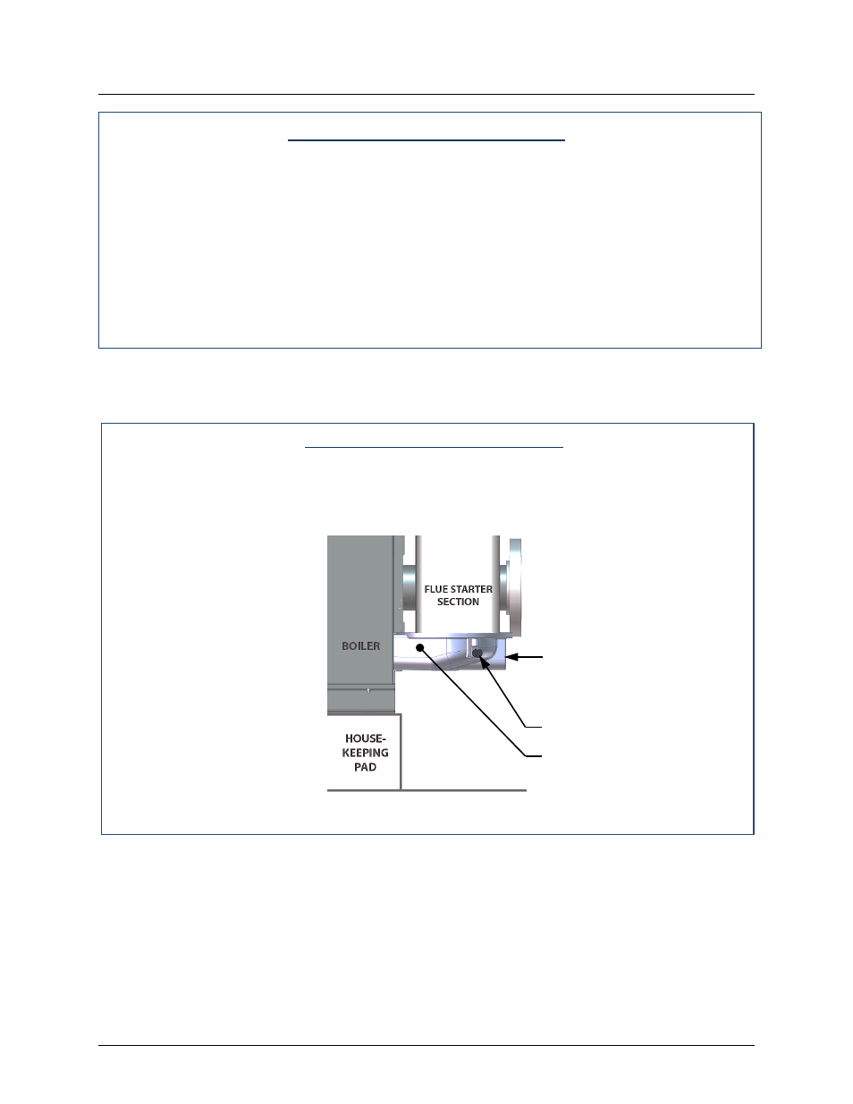
4.2.3 Accessing the Analyzer Probe Port
The unit contains a 1/4” NPT port on the side of the exhaust manifold as shown in Figure 4-2.
Prepare the port for the combustion analyzer probe as follows:
Accessing Analyzer Probe Port
1.
Refer to Figure 4-2 and remove the 1/4” NPT plug from the exhaust manifold.
2.
If necessary, adjust the stop on the combustion analyzer probe so it will extend mid-way
into the flue gas flow. DO NOT install the probe at this time.
Figure 4-2: Analyzer Probe Port Location
Condensate Drain
ANALYZER PROBE
EXHAUST