AERCO BMK 1000 User Manual
Page 129
Benchmark 750/1000 Boiler
CHAPTER 10. BOILER SEQUENCING TECHNOLOGY
OMM-0082_0J
AERCO International, Inc. • 100 Oritani Dr. • Blauvelt, NY 10913
Page 129 of 192
GF-130
Ph.: 800-526-0288
05/21/2014
10.3.4 Option 4 - Outdoor Reset with MODBUS Header Sensor AND MODBUS
Outdoor Sensor
NOTE: Both Header Sensor AND Outdoor Sensor must be wired. See the C-More Controller
User Manual, OMM-0032, GF-112 and ProtoNode User Manual, OMM-0080, GF-129 for more
information.
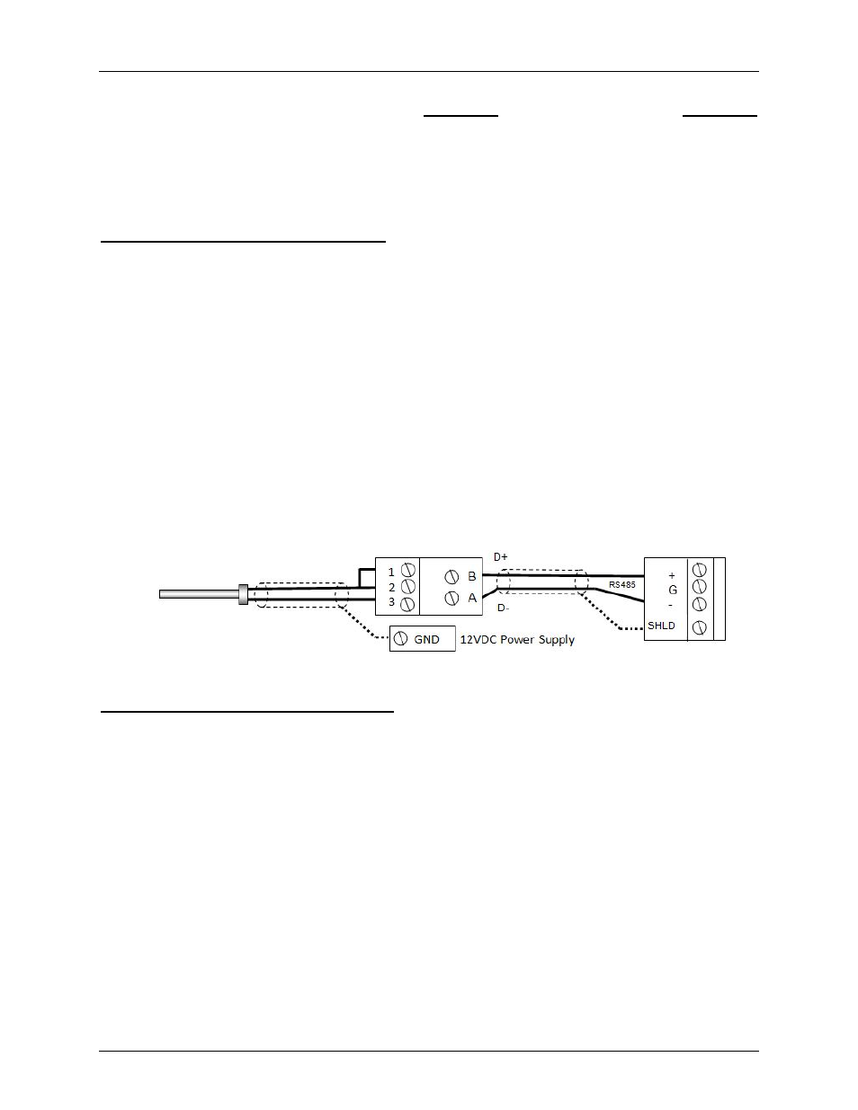
Step 1 - Modbus Header Sensor Wiring
1. Using Shielded pair 18 - 22 AWG cable, connect the Temperature Transmitter (AERCO P/N
65169) terminal Pin B to the RS485+ terminal on the I/O Box of any of the Boiler units, and
Pin A of the Temperature Transmitter to the RS485- terminal on the I/O Box of any of the
Boiler units.
2. Using Shielded pair 18 - 22 AWG cable, connect the Modbus Header Temperature Sensor
(AERCO PN 24410) to pins 2 and 3 of the Temperature Transmitter.
3. Install a jumper wire between pins 1 and 2 of the Temperature Transmitter.
NOTES:
• Polarity must be observed for the RS485 connections. The ground for the shield is at the
“SHLD” terminal in the I/O the Box.
• The header sensor must be installed between 2 and 10 feet downstream of the LAST boiler
in the plant’s supply water header.
• There is no polarity to be observed. The ground for the shield is at the power supply ground.
The sensor end of the shield must be left free and ungrounded.
Step 2 - Modbus Outdoor Sensor Wiring
1. If you have not already done so when installing the Modbus Header Sensor, use Shielded
pair 18 - 22 AWG cable to connect the Temperature Transmitter terminal Pin B to the
RS485+ terminal on the I/O Box of any of the Boiler units, and Pin A of the Temperature
Transmitter to the RS485- terminal on the I/O Box of any of the Boiler units.
2. Using Shielded pair 18 - 22 AWG cable, connect the Modbus Header Temperature Sensor
(AERCO PN 24410) to pins 2 and 3 of the Temperature Transmitter.
3. Install a jumper wire between pins 1 and 2 of the Temperature Transmitter.
NOTES:
• Polarity must be observed for the RS485 connections. The ground for the shield is at the
“SHLD” terminal in the I/O the Box.
• When mounting the Outdoor sensor, it must be located on the North side of the building
where an average outside air temperature is expected. The sensor must be shielded from
direct sunlight as well as impingement by the elements. The outdoor sensor may be wired
up to 200 feet from the boiler.
Temp Sensor PN 24410
Modbus Transmitter I/O Box