AERCO BMK 1000 User Manual
Page 18
Benchmark 750/1000 Boiler Installation, Operation & Maintenance Manual
CHAPTER 2 – INSTALLATION
Page 18 of 192
AERCO International, Inc. • 100 Oritani Dr. • Blauvelt, NY 10913
OMM-0082_0J
05/21/2014
Ph.: 800-526-0288
GF-130
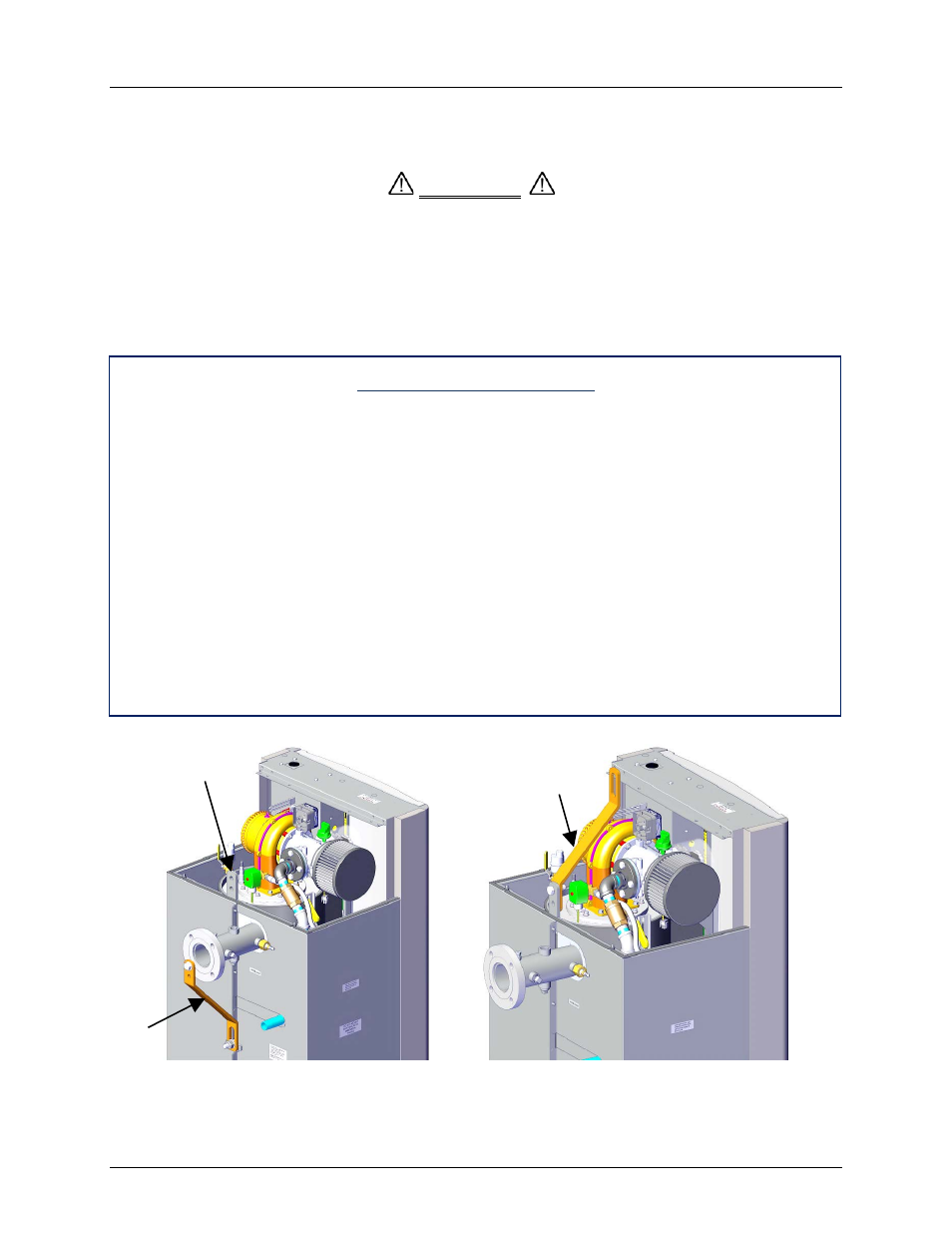
lifting tab is provided at the top of the unit’s heat exchanger as shown. This tab is used to attach
the lifting bar to the unit as follows:
WHEN LIFTING OR MOVING THE BOILER:
•
DO NOT ATTEMPT TO MANIPULATE THE BOILER USING THE
GAS TRAIN OR BLOWER
•
WHEN USING THE LIFTING TAB AND BAR, ENSURE THERE IS
NO LOAD PLACED ON THE GAS TRAIN OR BLOWER
Attachment of Lifting Bar
1.
Remove the lifting bar from its shipping location at the rear of the unit (Figure 2-2, View
A). Retain the attaching hardware consisting of two (2) hex head cap screws, hex nuts
and flat washers.
2.
Remove the top shroud from the boiler by grasping the handle on the top of the unit and
lifting straight up. Locate the lifting tab at the top-rear of the heat exchanger.
3.
Refer to Figure 2-2, View B and attach the lifting bar to the heat exchanger lifting tab
using the hardware removed in step 1. The upper end of the lifting bar containing the oval
cutout should be positioned over the top of the heat exchanger as shown.
4.
Using proper rigging equipment, capable of supporting 1000 to 1200 lbs., lift the boiler
and position it on the housekeeping pad.
5.
After the boiler is properly set on the pad, detach the lifting bar and replace the shroud on
the top of the unit.
6.
Retain the lifting bar for possible reuse at the installation site.
Figure 2-2: Boiler Lifting Provisions
WARNING
LIFTING BAR IN
LIFTING
POSITION
LIFTING
BAR IN
SHIPPING
POSITION
LIFTING TAB
VIEW B - LIFTING POSITION
VIEW A - SHIPPING POSITION