Maintenance – AERCO BMK 2.0 LN Nat. Gas for Mass. only User Manual
Page 53
MAINTENANCE
7.6 BURNER ASSEMBLY
The burner assembly is located at the top of the
unit. The burner assembly may be HOT. Allow
the unit to cool sufficiently before removing the
burner assembly.
It should be noted that the complete burner
assembly also includes the blower and air/fuel
valve in addition to the Benchmark 2.0 Low NOx
burner. It can be removed as one complete
assembly.
The following parts will be necessary for
reassembly after inspection:
Part No.
Description
81101
Burner Gaskets (2)
81047
Gas Injector Gasket (1)
81057
Blower Gasket (1)
81048
Flame Detector Gasket (1)
To inspect or replace the burner assembly:
1. Set
the
ON/OFF switch on the control panel,
to the OFF position. Disconnect AC power
from the unit and turn off the gas supply.
2. Remove the side and top panels from the
unit to provide access to the burner
assembly (Figure 7-3).
3. Disconnect the lead wire from the flame
detector. Unscrew and remove the flame
detector.
4. Disconnect the igniter cable from the igniter
contactor. Unscrew and remove the igniter.
5. Remove the two (2) 10-32 screws securing
the gas injector to the burner plate. Separate
the gas injector and gasket from the burner
plate.
6. Disconnect the gas train from the air/fuel
valve flange by removing the four 1/2” bolts
and nuts (Figure 7-3).
7. Disconnect the inlet air flex hose from the
air/fuel valve by loosening the hose clamp.
8. Remove the eight (8) 3/8-16 nuts from the
burner flange (Figure 7-3) using a 9/16”
wrench.
NOTE
The burner assembly is heavy, weighing
approximately 30 pounds.
9. Remove the burner assembly from burner
flange by pulling straight up.
10. Remove the grounding screw.
11. Remove and replace the burner gaskets.
12.
Beginning with the burner assembly
removed in step 9, reinstall all the
components in the reverse order that they
were removed.
13. Make sure to align the staged ignition
assembly, igniter and flame detector holes in
the burner plate with the heat exchanger top
head.
14. Check to ensure that the grounding screw is
reinstalled.
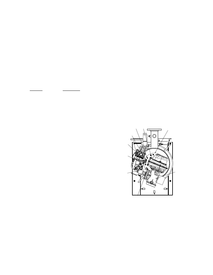
SPARK
IGNITER
3/8-16
NUTS
(8)
BLOWER
BURNER
PLATE
AIR/FUEL
VALVE
FLAME
DETECTOR
STAGED
IGNITION
ASSEMBLY
GAS
INJECTOR
1/2” BOLTS & NUTS
(4 PLACES) CONNECT AIR/
FUEL VALVE TO GAS TRAIN
(NOT SHOWN)
Figure 7-3
Burner Disassembly Diagram
7-3