KEYENCE KV Series User Manual
Page 8
6
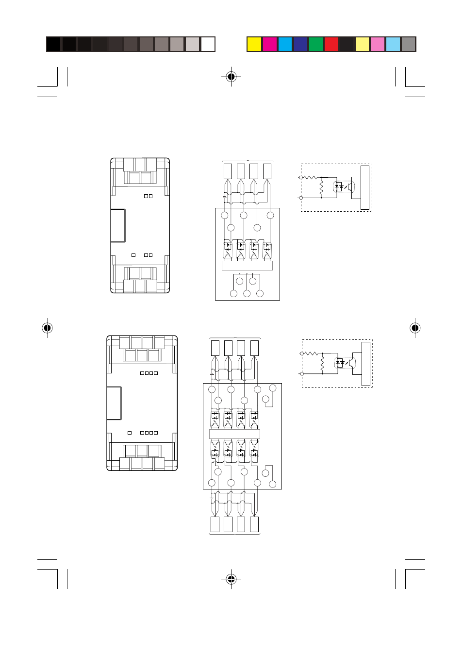
Terminal layout drawings and input circuit diagrams
KV-E4X (4-point expansion input unit)
■ Terminal layout drawing
■ Input circuit diagram
V1 V3 V5
C1
1
3
V2 V4
0
2
2
C1
1
3
0
V2
V5
V3
V1
V4
Internal Circuit
Three-wire
tipe
Three-wire
tipe
Three-wire
tipe
Three-wire
tipe
Sensor
Bro
wn
Blue
Blac
k
Bro
wn
Blue
Blac
k
Bro
wn
Blue
Blac
k
Bro
wn
Blue
Blac
k
0 to 3
C1
4.3 KΩ
510 Ω
Photocoupler
insulation
• V1 to V5 are short-
circuited inside
(so they can be used as
a relay terminal block).
Internal circuit
KV-E8X (8-point expansion input unit)
■ Terminal layout drawing
■ Input circuit diagram
V1
V2
2
C1
1
3
0
V3
V4
6
C2
5
7
4
Three-wire
tipe
Three-wire
tipe
Three-wire
tipe
Three-wire
tipe
Three-wire
tipe
Three-wire
tipe
Three-wire
tipe
Three-wire
tipe
Sensor
Brown
Blue
Black
Brown
Blue
Black
Brown
Blue
Black
Brown
Blue
Black
Brown
Blue
Black
Brown
Blue
Black
Brown
Blue
Black
Brown
Blue
Black
Internal Circuit
Sensor
C2
5
7
V4
4
6
V3
C1
1
3
V2
0
2
V1
0 to 3
4 to 7
C1
C2
4.3 KΩ
510 Ω
• C1 and C2 are each
independent.
• V1 to V2 and V3 to V4 are
short-circuited inside
respectively (so they can
be used as relay terminal
plates).
Photocoupler
insulation
Internal circuit