14 output specifications, Terminal layout drawings and i/o circuit diagrams, Kv-e4xr (relay output type) – KEYENCE KV Series User Manual
Page 16: Output circuit diagram
14
Output specifications
KV-E4XR (Relay output type)
m
e
t
I
s
n
o
i
t
a
c
i
f
i
c
e
p
S
e
p
y
t
t
u
p
t
u
O
y
a
l
e
R
d
o
h
t
e
m
n
o
i
t
c
e
n
n
o
c
l
a
n
r
e
t
x
E
e
t
a
l
p
l
a
n
i
m
r
e
T
e
g
a
t
l
o
v
d
a
o
l
d
e
t
a
R
)
d
a
o
l
e
v
i
t
s
i
s
e
r
(
A
4
)
d
a
o
l
e
v
i
t
c
u
d
n
i
(
A
2
C
D
V
0
3
/
C
A
V
0
5
2
t
n
e
r
r
u
c
t
u
p
t
u
o
d
e
t
a
R
n
o
m
m
o
c
/
A
4
)
d
a
o
l
e
v
i
t
s
i
s
e
r
(
t
n
i
o
p
/
A
4
)
d
a
o
l
e
v
i
t
c
u
d
n
i
(
t
n
i
o
p
/
A
2
e
c
n
a
t
s
i
s
e
r
N
O
m
0
5
Ω
s
s
e
l
r
o
d
o
h
t
e
m
n
o
m
m
o
C
n
o
m
m
o
c
/
s
t
n
i
o
p
4
F
F
O
(
e
m
i
t
n
o
i
t
a
r
e
p
o
g
n
i
s
i
R
➞
)
N
O
s
s
e
l
r
o
s
m
0
1
N
O
(
e
m
i
t
n
o
i
t
a
r
e
p
o
g
n
i
l
l
a
F
➞
)
F
F
O
s
s
e
l
r
o
s
m
0
1
e
f
i
l
e
c
i
v
r
e
s
y
a
l
e
R
e
r
o
m
r
o
s
e
m
i
t
0
0
0
,
0
0
0
,
0
2
:
l
a
c
i
n
a
h
c
e
M
,
)
n
i
m
/
s
e
m
i
t
0
2
(
e
r
o
m
r
o
s
e
m
i
t
0
0
0
,
0
0
1
:
l
a
c
i
r
t
c
e
l
E
t
n
e
m
e
c
a
l
p
e
r
y
a
l
e
R
d
e
w
o
ll
a
t
o
N
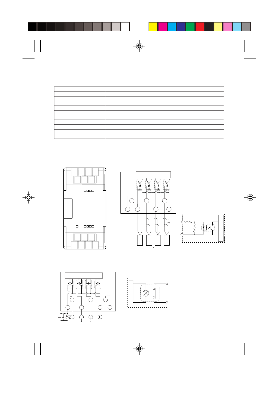
Terminal layout drawings and I/O circuit diagrams
KV-E4XR (Relay output type)
■ Terminal layout drawing
■ Input circuit diagram
C2 Y1 Y3 V4
Y0 Y2 V3
C1 X1 X3 V2
X0 X2 V1
V1
V2
X2
C1
X1
X3
X0
Sensor
Internal Circuit
Three-wire
tipe
Brown
Brown
Blue
Black
Three-wire
tipe
Blue
Black
Brown
Three-wire
tipe
Blue
Black
Brown
Three-wire
tipe
Blue
Black
X0 to X3
C1
4.3 KΩ
510 Ω
Internal circuit
• V1 to V2 and V3 to V4 are
short-circuited inside
(so they can be used as
relay terminal plates).
Photocoupler
insulation
■ Output circuit diagram
Y3
Y2
Y1
Y0
C2
V4
V3
Internal circuit
Y0 to Y3
C2
• V1 to V2 and V3 to V4 are short-circuited
inside (so they can be used as relay
terminal plates).
Internal circuit