15 kv-e4xt(p) (transistor output type), Output circuit diagram – KEYENCE KV Series User Manual
Page 17
15
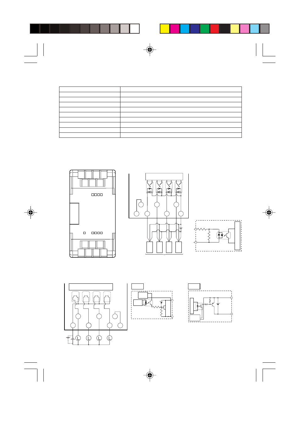
KV-E4XT(P) (Transistor output type)
m
e
t
I
s
n
o
i
t
a
c
i
f
i
c
e
p
S
e
p
y
t
t
u
p
t
u
O
)
P
N
P
(
/
)
N
P
N
(
r
o
t
s
i
s
n
a
r
T
d
o
h
t
e
m
n
o
i
t
c
e
n
n
o
c
l
a
n
r
e
t
x
E
e
t
a
l
p
l
a
n
i
m
r
e
T
e
g
a
t
l
o
v
d
a
o
l
d
e
t
a
R
C
D
V
0
3
t
n
e
r
r
u
c
t
u
p
t
u
o
d
e
t
a
R
)
P
N
P
(
t
n
i
o
p
/
A
3
.
0
,
)
N
P
N
(
t
n
i
o
p
/
A
5
.
0
s
u
t
a
t
s
F
F
O
n
i
t
n
e
r
r
u
c
k
a
e
L
0
0
1
µ
s
s
e
l
r
o
A
s
u
t
a
t
s
N
O
n
i
e
g
a
t
l
o
v
l
a
u
d
i
s
e
R
s
s
e
l
r
o
V
8
.
0
d
o
h
t
e
m
n
o
m
m
o
C
n
o
m
m
o
c
/
s
t
n
i
o
p
4
F
F
O
(
e
m
i
t
n
o
i
t
a
r
e
p
o
g
n
i
s
i
R
➞
)
N
O
0
5 µ
s
s
e
l
r
o
s
N
O
(
e
m
i
t
n
o
i
t
a
r
e
p
o
g
n
i
l
l
a
F
➞
)
F
F
O
0
5
2
µ
s
s
e
l
r
o
s
➮ For more about the general specifications, refer to "Specifications" on page 4.
C2 Y1 Y3 V4
Y0 Y2 V3
C1 X1 X3 V2
X0 X2 V1
V1
V2
X2
C1
X1
X3
X0
Sensor
Internal Circuit
Three-wire
tipe
Brown
Brown
Blue
Black
Three-wire
tipe
Blue
Black
Brown
Three-wire
tipe
Blue
Black
Brown
Three-wire
tipe
Blue
Black
X0 to X3
C1
4.3 KΩ
510 Ω
• V1 to V2 and V3 to V4 are
short-circuited inside (so
they can be used as relay
terminal plates).
Internal circuit
Photocoupler
insulation
■ Output circuit diagram
Y3
Y2
Y1
Y0
C2
V4
V3
*
Internal circuit
Y0 to Y3
C2
Insultating
power
supply
Internal
circuit
• V1 to V2 and V3 to V4 are short-circuited inside
(so they can be used as relay terminal plates).
KV-E4XT(P) (Transistor output type)
■ Terminal layout drawing
■ Input circuit diagram
* For KV-E4XTP
NPN
PNP
Insultating
power
supply
Internal circuit
C2
Y0 to Y3