Contact protection – KEYENCE KV Series User Manual
Page 21
19
■ When I/O signal lines cannot be separated from the wiring for power
In such a case, perform grounding on the KV side using batch-shielded
cables. (In some environments, grounding should be performed on the
reverse side of the KV.)
■ Terminal
The terminal screws used are M3. When performing wiring with crimp-style
terminals, use the following ones.
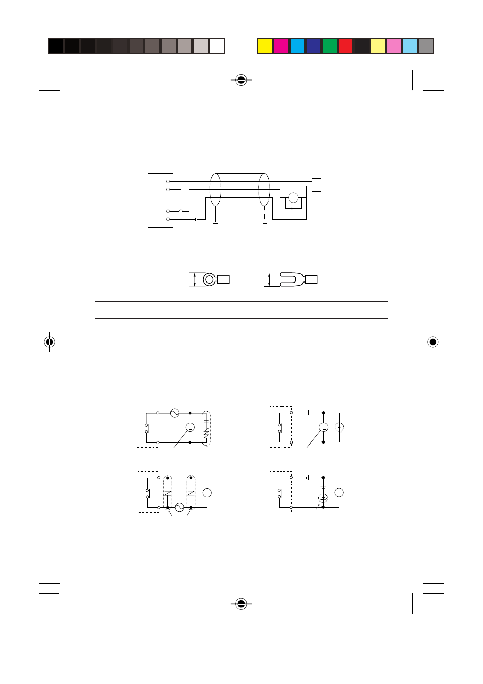
CONTACT PROTECTION
If inductive loads such as clutches, motors, and solenoids are used, a rush
current may flow when the load power supply is turned on, or a counter
electromotive voltage may be generated when the load power supply is shut
down. The rush current and the counter electromotive voltage can contribute
considerably to shortening the service life of the contacts. To prevent this
from happening, provide a contact protection circuit.
Contact protection circuit examples
When the supply voltage is 24 to 48 V, provide a protection circuit in position
“b”. When the supply voltage is 100 to 200 V, provide a protection circuit in
position “a”.
6.0 maximum
6.0 maximum
M3
RL
24 V DC
KV
Input
Shielded cable
Sensor
Output
Ground
a
b
For AC load 1
Zener diode
For DC load 2
Contact
Varistor
Contact
For AC load 2
For DC load 1
Contact
Load
Diode
CR circuit
Load
Contact