Outputting the total status – KEYENCE CV-X Series User Manual
Page 3
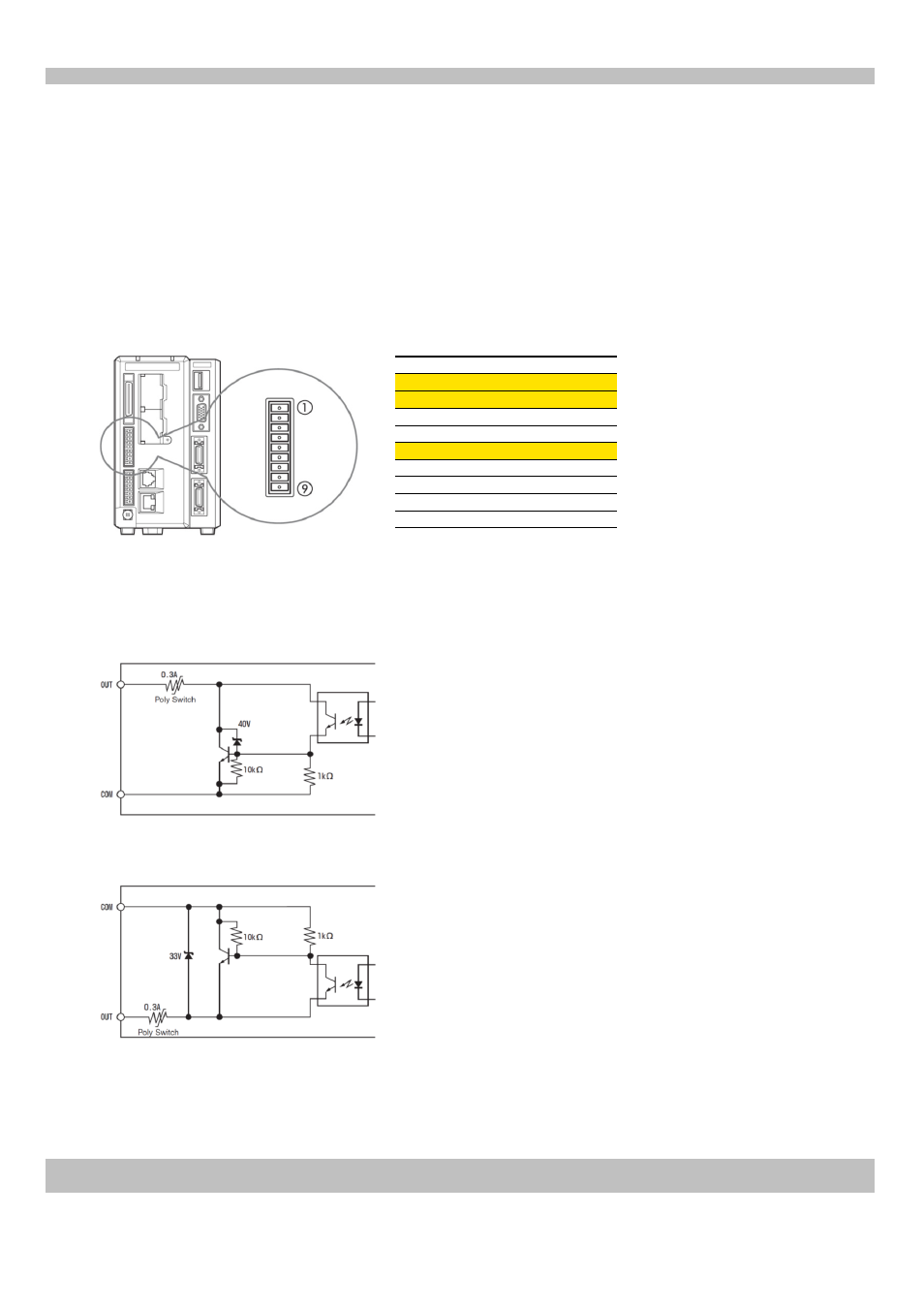
COMOUT1 (COMOUT)
5
3
4
No.
OUT22 (STO)
OUT23 (OR)
F_OUT2 (ERR)
F_OUT3 (RUN)
1
2
369GB
KEYENCE CORPORATION. Vision System Division
‐ 3 ‐
www.keyence.com
Terminal name *1
F_OUT0 (FLS1)
6
7
8
F_OUT1 (FLS2)
COMOUT_F+ (COM1F+)
COMOUT_F‐ (COM1F‐)
9
Outputting the Total Status
Perform the following wiring to output the total status of inspections.
This section explains how to wire the terminal block "OUT22:STO" "OUT23:OR" to a PLC or relay.
(The terminal block is attached to the main unit)
1. Wiring
Suitable wire: AWG 16 to 28 Terminal block screw torque: 0.25 Nm or less
*1 The characters in brackets in the terminal name are the characters written on the supplied terminal blocks when shipped.
Controller terminal block (OUT connector)
Output circuit diagram (NPN output type)
Output circuit diagram (PNP output type, controllers with a "P" at the end of the part number)
•
Maximum applied voltage: 30 V
•
Maximum sink current: 50 mA
•
Leakage current: 0.1 mA or less
•
Residual voltage:
1.4 V or less (50 mA)
1.0 V or less (20 mA)
•
Maximum applied voltage: 30 V
•
Maximum sink current: 50 mA
•
Leakage current: 0.1 mA or less
•
Residual voltage:
1.4 V or less (50 mA)
1.0 V or less (20 mA)
(No. 1, 2)
(No. 5)
(No. 5)
(No. 1, 2)