KEYENCE CV-X Series User Manual
Page 10
KEYENCE CORPORATION. Vision System Division
‐ 10 ‐
www.keyence.com
39 OUT21 (OUT_DATA15)
White
40 COMOUT2
Black
37 OUT19 (OUT_DATA13)
Purple
29
↓
36 OUT18 (OUT_DATA12)
Blue
Blue
38 OUT20 (OUT_DATA14)
Gray
27 OUT9 (OUT_DATA3)
Purple
28 OUT10 (OUT_DATA4)
Gray
24 OUT6 (OUT_DATA0)
Yellow
OUT11 (OUT_DATA
5)
White
30 OUT12 (OUT_DATA6)
Black
26 OUT8 (OUT_DATA2)
Color
Input
25 OUT7 (OUT_DATA1)
Green
17 COMIN2 (COMIN2)
Purple
No.
Terminal name
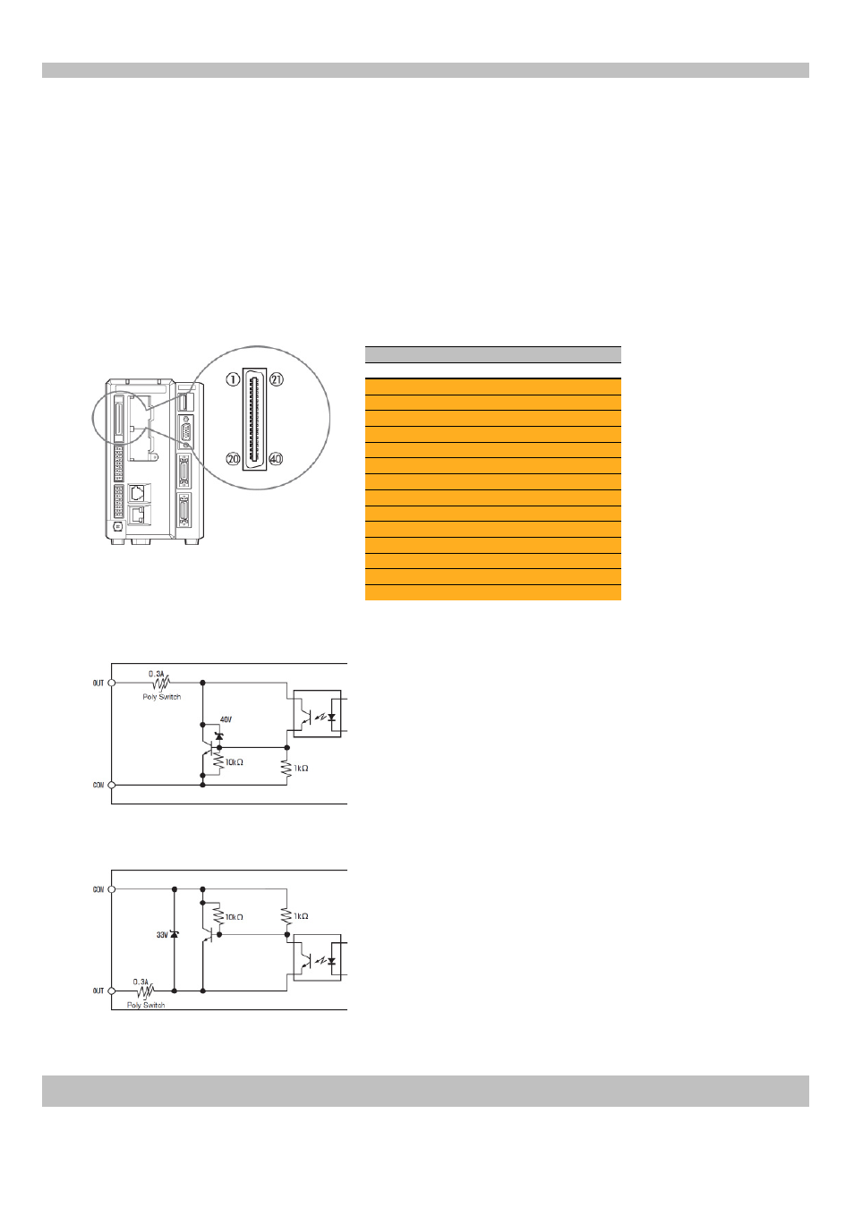
Outputting the individual status of each tool (parallel I/O)
Perform the following wiring to output the individual status of tools from the I/O terminal (parallel I/O interface).
This section describes the necessary terminal (outputs: OUT6 to 21 (OUT_DATA0 to 15), COMOUT2) wiring for
outputting the individual status of tools from the I/O terminal. (The parallel I/O cable, OP‐51657, is sold
separately)
1. Wiring
Suitable wire: AWG 16 to 28
Terminal block screw torque: 0.25 Nm or less
Controller (parallel I/O interface)
Output circuit diagram (NPN output type)
Output circuit diagram (PNP output type, controllers with a "P" at the end of the part number)
‐ Maximum applied voltage: 30 V
‐ Maximum sink current: 50 mA
‐ Leakage current: 0.1 mA or less
‐ Residual voltage:
1.4 V or less (50 mA)
1.0 V or less (20 mA)
‐ Maximum applied voltage: 30 V
‐ Maximum sink current: 50 mA
‐ Leakage current: 0.1 mA or less
‐ Residual voltage:
1.4 V or less (50 mA)
1.0 V or less (20 mA)
(No. 1, 2)
(No. 5)
(No. 5)
(No. 1, 2)