Installation, Installation controller, Sensor head – KEYENCE LB-1000(W) User Manual
Page 9: Connections ■ description of dip switches
9
INSTALLATION
Controller
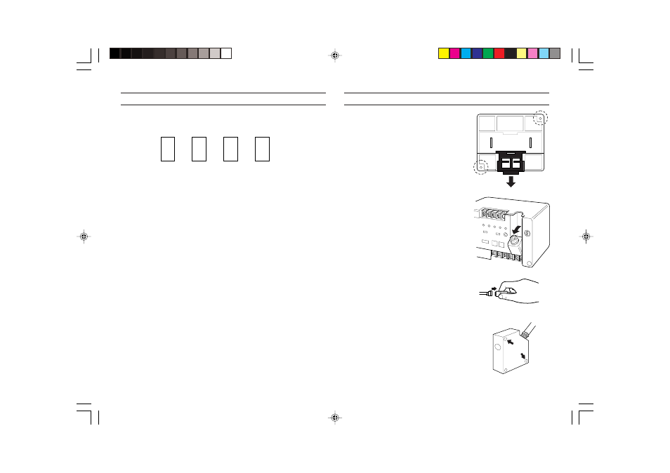
The controller can be mounted to a DIN
rail. When mounting or removing the
controller, pull the claw (bottom center) in
the direction of the arrow. The controller
can also be screw-mounted using the
mounting holes provided.
Sensor head
1. First, tilt the receptacle of the controller
forward, as shown.
2. To attach the connector, gently press
the plug into the receptacle, turn the
plug left or right to locate the engaging
position, then press until you hear a
click.
(Also follow this procedure to connect an
extension cable or sensor head cable to the
receptacle.)
To remove the connector, hold the
connecting sleeve as shown, and pull it
out in the direction of the arrow.
Mounting the sensor head
The sensor head has mounting holes, as
shown in the figure on the right.
Secure the sensor head using M4
screws.
(LB-301 has three mounting holes.)
CONNECTIONS
■ Description of DIP switches
1 RESPONSE speed mode selector switch
To use the FUZZY logic control circuit, set the switch to FUZZY.
2 Interference suppression function selector switch
To have 2 sensors emit laser beams alternately, set the switch of one
controller to MAIN and the other to SUB.
3 Laser power control selector switch
MAX:
Laser emission power is set to maximum.
AUTO: Laser emission power is controlled according to changes in
received light quantity. (Selecting AUTO mode prevents
fluctuations in received light quantity caused by surface
unevenness from affecting target measurement.
4 AUTO ZERO setting lock
1
2
3
4
MAIN
FUZZY
SUB
AUTO
LOCK
DIP
RESPONSE
MANUAL
ZERO
FREE
LASER
POWER
MAX