Setting, Auto zero/output adjustment, Output adjustment – KEYENCE LB-1000(W) User Manual
Page 10
10
SETTING
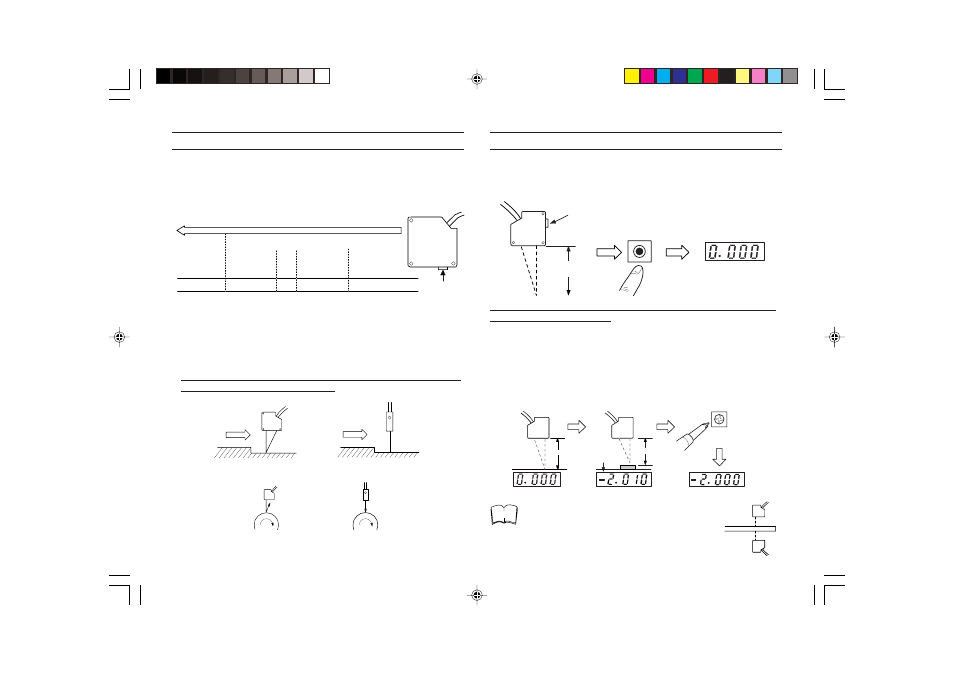
1. Adjust the distance between the sensor head and target and confirm
the position with the LASER ON alarm LED. Set the sensor head so
that the laser emitting surface is parallel to the measuring surface of
the target, then secure it in place. (See figure below.)
When the LED lights green, the target is in the center area of the
measuring range.
LB-041: approx. 40 mm
LB-081: approx. 80 mm
LB-301: approx. 300 mm
2. Adjust orientation of the sensor head (for a moving target).
Be sure to mount the sensor head as shown in the right-hand figure
below to ensure stable measurement.
Example: Step detection
Example: Eccentricity measurement
AUTO ZERO/OUTPUT ADJUSTMENT
Press the AUTO ZERO key to reset the output voltage to zero at the
mounting position.
Example: LB-041
AUTO ZERO setting is possible from external terminals (connecting the
6 terminal to a GND terminal).
* The AUTO ZERO function can be used when the DIP switch No. 3 of
the controller is set to FREE (top setting).
Output adjustment
If the output voltage value is not in proportion with the target displace-
ment, adjust the output voltage using the SPAN adjustment trimmer.
Example: LB-041
When a sensor is positioned on both sides of a
target for measurement, be sure to adjust the span
of each sensor separately.
Incorrect
Correct
Incorrect
Correct
V
The LED light green.
Approx.
40 mm
ZERO
Panel meter
*12 mA for
current output.
V
V
40 mm
38 mm
V
SPN-ADJ
adjustment +0.010.
Change by 2 mm
(To change
-2.010 to -2.000.)
Span adjustment
Note
Measuring range
LASER ON
alarm LED
Red
Yellow
Green
Yellow
Red
Center
Distance between sensor head and target
Out of
measuring
range
(Operating range)
Out of
measuring
range
(Operating range)