KEYENCE LB-1000(W) User Manual
Page 13
13
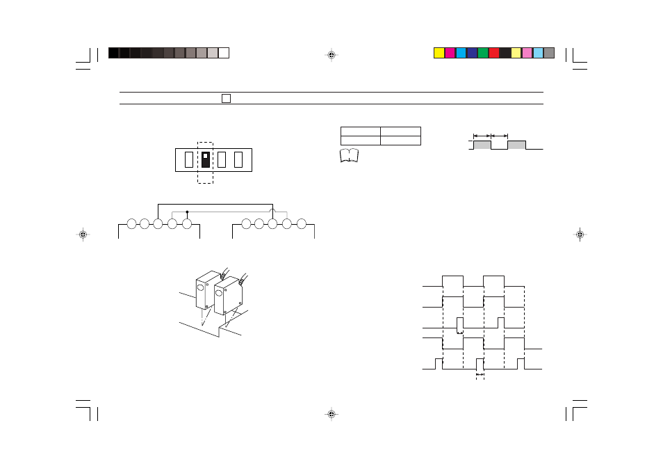
SETTING DIP SWITCH 2 (INTERFERENCE SUPPRESSION FUNCTION)
When using 2 sensor heads in close proximity, set the DIP switch of one
controller to MAIN, and that of the other to SUB to suppress interference.
(This can also be used for synchronized measurement.)
Wire as follows. (Upper terminals of controller)
Example: Step measurement using 2 sensors.
Alternating oscillation frequency and ON/OFF ratio (all models)
Frequency
ON/OFF ratio
30Hz
1 : 1
• Controller set to MAIN: Monitor output is retained when the synchro-
nous (timing) pulse is OFF.
Controller set to SUB:
Monitor output is retained when the synchro-
nous (timing) pulse is ON.
• Controller set to MAIN: The laser beam is emitted at the rising edge
of the synchronous (timing) pulse, but the
signal is not read for 8 to 10 ms. Effective
measurement occurs only during the last half
of the synchronous (timing) pulse (6 to 8 ms).
Controller set to SUB:
The laser beam is emitted at the falling edge
of the synchronous (timing) pulse, but the
signal is not read for 8 to 10 ms. Effective
measurement occurs only during the last half
of the synchronous (timing) pulse (6 to 8 ms).
DIP
1
2
3
4
10
11
12
13
14
10
11
12
14
13
Set DIP switch 2 to MAIN
Set DIP switch 2 to SUB
A
B
ON
OFF
Synchronous
(timing) pulse
Note
Synchronous
(timing) pulse (TIM OUT)
Controller set to MAIN
Laser emission
Controller set to SUB
Laser emission
Controller set to SUB
Data reading
Approx.
6 to 8 ms
Approx. 6 to 8 ms
Controller set to MAIN
Data reading