Holtgreven GSE-375 User Manual
Page 83
77
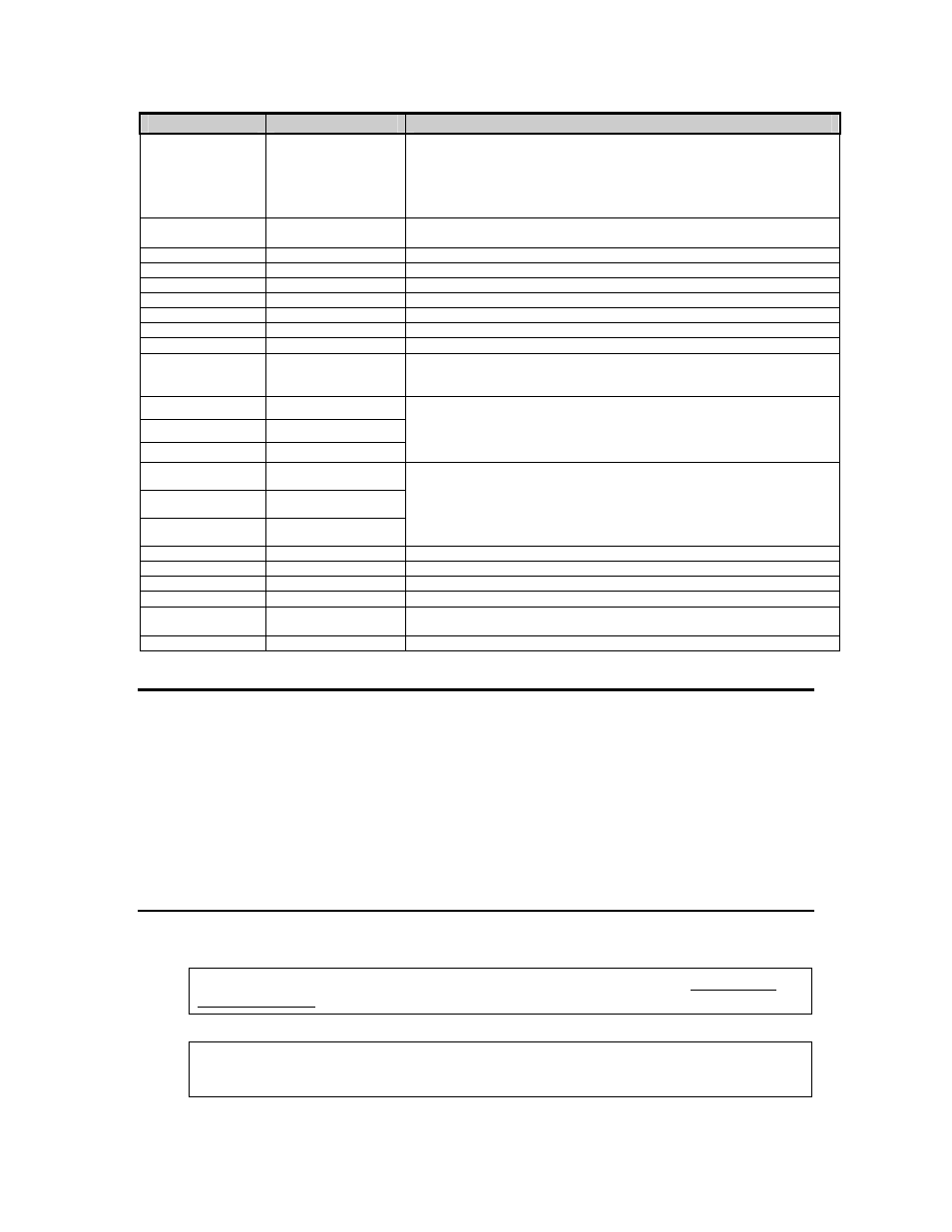
PARAMETER
NAME
DESCRIPTION
61117
61120
AiN1 ~ NrOff
-11035
AiN8 ~ NrOff
-14800
A/D non-ratio-metric offset compensation.
61121
Vre f~ NrOff
-12739
A/D reference voltage compensation.
61200
10oFF
Analog option 0 – 10V Zero offset value.
61201
10Gn
Analog option 0 – 10V Full scale gain value.
61202
0oFF
Analog option 0 – 20mA Zero offset value.
61203
0Gn
Analog option 0 – 20mA Full scale gain value.
61204
4oFF
Analog option 4 – 20mA Zero offset value.
61205
4Gn
Analog option 4 – 20mA Full scale gain value.
61206
Srln
Analog option board serial number.
62000
Dsply ~ Test
8.8.8.8.8.8.
Display test. Press [TARE] or [SAMPLE/Enter] to illuminate all segments.
Continue pressing [TARE] or [SAMPLE/Enter] to cycle through various
patterns.
62001
Spt 1 ~ Disbl
62002
Spt 2 ~ Disbl
62003
Spt 3 ~ Disbl
Allows setpoint status to be changed by pressing [TARE] or
[SAMPLE/Enter] while viewing this parameter. Requires that setup was
entered using the access code.
62004
Analg ~ 0- 10v
62005
Analg ~ 0-20A
62006
Analg ~ 4-20A
Allows the analog output to be changed by pressing [TARE] or
[SAMPLE/Enter]. Output will toggle through 0, 25, 50 and 100 percent
while viewing this parameter. Requires that setup was entered using the
access code (see Analog Board Diagnostic and Test Procedures on page
77).
64000
Send ~ Setup
Transmits all setup information out the communication port.
64100
LnCnt ~ 0
Received setup line count.
64101
ErCnt ~ 0
Received setup error count.
64102
1stEr ~ None!
Parameter of the first setup receive error.
65001
Deflt ~ All
Default All. Sets all parameters to factory default settings. Press [TARE]
or [SAMPLE/Enter] to initiate default.
65002
Deflt ~ -CAL
Same as above, except calibration is retained.
A
A
/
/
D
D
C
C
a
a
l
l
i
i
b
b
r
r
a
a
t
t
i
i
o
o
n
n
P
P
r
r
o
o
c
c
e
e
d
d
u
u
r
r
e
e
The Model 370/375 Analog-to-Digital Converter (A/D) is calibrated at the factory to ensure a
stable, linear response to the load cell signal. This calibration procedure calculates critical values
that are permanently stored in parameters P61110 - P61121. The A/D calibration should not be
confused with the standard weight calibration. It should never be necessary to recalibrate the
A/D. However, if the values stored at parameters P61110 - P61121 appear to be reset to
0.00000 and/or 1.00000, then A/D recalibration is necessary. Contact GSE Scale Systems or
your local authorized GSE distributor for more information on this procedure.
A
A
n
n
a
a
l
l
o
o
g
g
B
B
o
o
a
a
r
r
d
d
D
D
i
i
a
a
g
g
n
n
o
o
s
s
t
t
i
i
c
c
s
s
A
A
n
n
d
d
T
T
e
e
s
s
t
t
P
P
r
r
o
o
c
c
e
e
d
d
u
u
r
r
e
e
s
s
The following test procedures affect the analog output signal levels. Be sure to disconnect all
peripheral devices attached to the analog option card.
Test equipment needed: precision DC voltmeter, 500 ohm precision resistor. The 500 ohm
resistor must meet the following specifications: .01% tolerance and 5ppm temperature
coefficient.