Chapter 2, Ption, Nstallation – Holtgreven GSE-375 User Manual
Page 13
7
Chapter 2:
O
PTION
I
NSTALLATION
This chapter will provide detailed instructions on installing each option. Additional hardware may
be needed for the Model 370/375 depending on which options you will be installing.
Also this chapter provides instructions on how to configure all Model 370 / 375 options. This
includes setup mode parameters, connections, calibration and testing.
C
C
o
o
m
m
m
m
u
u
n
n
i
i
c
c
a
a
t
t
i
i
o
o
n
n
RS-485 N
ETWORKING
The module converts the standard RS-232 communication on comm port 1 to RS-485. However
the advantage of using the RS-485 module, aside from the ability to transmit over long distances,
is the ability to network multiple indicators or parts counters using the same communication wires.
When networking indicators or parts counter, it is necessary to set up a network address for each
scale. The network module itself does not require addressing, rather each indicator or parts
counter must be enabled for network addressing in the setup mode. Refer to page 26 for details
on the RS-485 enable parameter (P250) and the network address parameter (P251).
Installation Instructions
1. DISCONNECT POWER! UNPLUG THE MODEL 370/375 TO INSURE DAMAGE WILL NOT
OCCUR DURING OPTION INSTALLATION.
2. Remove the six 8 mm screws (size) from the bottom plate. Separate the top enclosure from
the bottom plate.
3. Remove the IC chip and white jumper from the U4 socket on the main board.
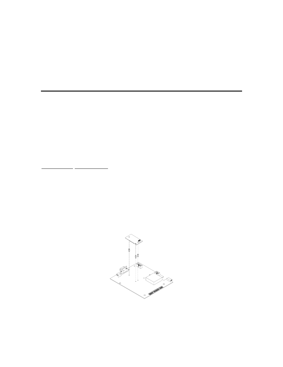
4. Snap in the plastic spacers into the three mounting holes surrounding the U4 socket. Refer
to Figure 2-1.
5. Gently press the option board into the socket and make sure the board snaps onto the
standoffs.
6. Reinstall the enclosure bottom plate.
Figure 2-1: RS-485 / 20 mA Option Installation
RS-485 Connections (Comm Port 1)
The Model 370/375 will be connected to a peripheral via the DB 9 connector on comm port 1.
Refer to Table 2-1 for wiring connections.