Holtgreven GSE-375 User Manual
Page 8
2
Install the new load cell by placing it in the load cell cavity. Fasten the load cell by installing the
bolts on the bottom plate. Reinstall the spider assembly. NOTE: When exchanging a load cell
with another, the overload stop and corner overloads must be reset. Refer to Table 1-1 for
setting values.
Table 1-1: Load Cell Overload Settings
Load Cell Stop
Set to
Load Cell Center Overload
120 % of full scale
Corner Overloads
60 % of full scale
L
OAD
C
ELL
C
ONNECTIONS
The load cell cable connects to J10 of the main board. The J10 connector is accessible from the
load cell cavity of the Model 370/375 enclosure.
Table 1-2: Load Cell Connection to Main Board
Pin Designation
Function
1 Shield
2 -
Sense
3 +
Sense
4 -
Signal
5 +
Signal
6 -
Excitation
7 +
Excitation
K
K
e
e
y
y
p
p
a
a
d
d
All of the keys perform different functions. Some keys have more than one function.
M
ODEL
370
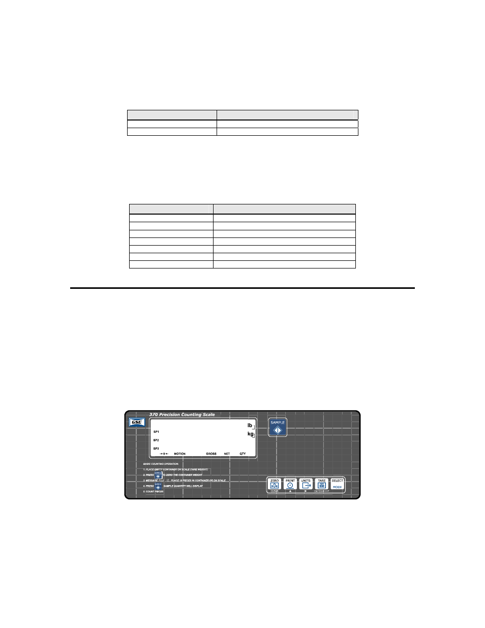
The Model 370 offers a 6-button durable and versatile Polymeric switch plate with large keys for
ease of use. The keypad is easily cleaned with a damp cloth or non-abrasive cleaner. Each key is
assigned two distinct functions. Various key combinations are also used. Each key has secondary
functions; allowing an operator to enter target values, perform piece samples, access setup
parameters, etc.
Figure 1-4: Model 370 Keypad
Functions
The Model 370 keypad performs different functions in the Weigh Mode, the Setup Mode, and the
Calibration Mode. Secondary functions for each key allow you to perform additional tasks.