Holtgreven GSE-375 User Manual
Page 17
11
Connected Devices
While 20 mA current loops can allow for more than one transmitter and/or receiver, the Model
370/375 and/or option board do not include any address recognition or collision avoidance and/or
detection to promote this usage. If the 20-mA loop is intended to be used in this manner, proper
planning for these issues is required.
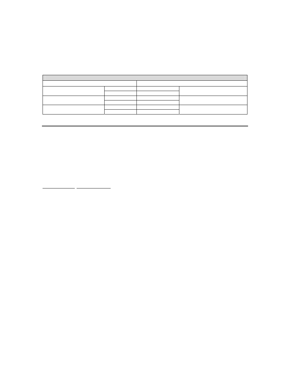
Table 2-2: Connecting to External Devices
Typical Installations
Model 370/375
External Device
TP RX+
Passive 20 mA Output
TXO RX-
Active 20 mA Input
RXI RX+
Passive 20 mA Input
RX RX-
Active 20 mA Output
TXO RX+
Active 20 mA Output
TA RX-
Passive 20 mA Input
A
A
n
n
a
a
l
l
o
o
g
g
O
O
u
u
t
t
p
p
u
u
t
t
O
O
p
p
t
t
i
i
o
o
n
n
This section provides procedures for installing and configuring the analog output module.
The analog output modules enable the Model 370/375 to generate a 0-10VDC, active 0-20mA or
active 4-20mA output signal corresponding to the value of most operating parameters. For
parameter setup see page 35. For details on testing and troubleshooting see page 77. For
analog output calibration see page 71. Requires an option mounting bracket kit (24370B-300A0)
for internal installation.
Installation Instructions
1. DISCONNECT POWER! UNPLUG THE MODEL 370/375 TO INSURE DAMAGE WILL NOT
OCCUR DURING OPTION INSTALLATION
2. Remove the (6) 38-31-8710 M5 x 0.8 x 10 mm screws from the enclosure bottom plate and
set it aside.
3. Discard the mounting hardware provided with the analog output kit and use the hardware
provided with the option-mounting bracket kit. Refer to page 13 for parts included with this
kit.
4. Snap in the (4) nylon spacers in the 4 holes either to the right of the notch or the left of the
notch in the option mounting bracket.
5. Position the Analog Output Option Board on the spacers so the ribbon cable points away
from the notch on the option-mounting bracket. Carefully press the analog output option onto
the spacers.
6. Install the (4) nylon hex nuts to secure the option board. Refer to Figure 2-3 for details.
7. If a setpoint option is also being used, connect the 6" option ribbon cable from J1 of the
analog output option board to J1 of the setpoint option board.
8. Connect the 22-30-25520 6.5" ribbon cable (optional) to from J2 of the analog output board to
J3 of the main board.
9. Install the option-mounting bracket in the Model 370/375 enclosure. Refer to page 13 for
option mounting bracket installation instructions.
10. Connect all necessary wiring to the Analog Output Option Board.
11. Reinstall the enclosure bottom plate.