Panasonic WV-CPR650 User Manual
Page 32
Attention! The text in this document has been recognized automatically. To view the original document, you can use the "Original mode".
6. The VS gen-lock mode has its own menu for hori
zontal phase adjustments. When the cable length
of the video output or the gen-lock input is
changed, the horizontal phase must be re-adjust
ed,
7. The line-lock mode has its own menu for line-lock
vertical phase adjustment. If the camera installa
tion is relocated, check the vertical phase adjust
ment again since the AC line phase may be differ
ent.
3. Confirm that the INT parameter changed to EXT
(VBS) on the menu.
Caution: The gen-lock input signal should meet
the EIA RS-170A specifications and should
not contain jitter, such as a VCR playback sig
nal, as it could disturb synchronization,
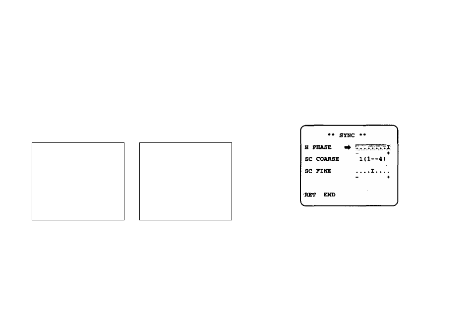
4, After confirming that the cursor is on EXT (VBS),
press E]. The phase adjustment menu appears
on the monitor.
6-1. VBS Gen-lock Mode (EXT(VBS))
—
>
r
** CAW BET UP ••
** CAB SET UP ••
CiUfERA ZD
OFF n
CAHERA ZD
OFF
*1
ALC/EDC
ALC 1
ADC/EDC
ALC n
SHUTTER
—
SHUTTER
—
AGC
ON
k
AQC
ON
SENS CP
OFF
4
SENS UP
OFF
SYttC
iWrr
SYNC
SXT WHITE BAI. ATW n WHITE BAD ATW “1 KOTION DET OFF "1 KOTION DET OFF *1 LENS DRIVE DC LENS DRIVE DC RET RET 1. Move the cursor to the SYNC parameter and select INT. 2. Connect the coaxial cable for the blackburst or composite color video signal to the gen-lock input 5. Move the cursor to H PHASE. The cursor starts blinking. 6. Supply the video output signal of the camera to be adjusted and the reference gen-lock input signal to a dual-trace oscilloscope. 7. Set the oscilloscope to the horizontal rate and expand the horizontal sync portion on the oscillo -30-
connector.
scope.