Power-up and front panel functions – CANOGA PERKINS 9145 Network Interface Device User Manual
Page 17
9145 Network Interface Device
2-5
8. Connecting Ethernet Cables to UTP Interface Modules: Plug the shielded Ethernet
Cable into the UTP Connector on the Interface Module. Be sure the locking tab properly
seats. If the locking tab is broken or missing, replace the cable.
Caution: To maintain Lighting and Power Shorting protection, always use
Ethernet Cables with a proper Ground Shield cable and connector.
Canoga Perkins recommends you label the cables with the circuit number or other
identifier and the signal direction on optical cables (TX or RX).
Canoga Perkins recommends that you determine and record optical link attenuation
and transmission power before starting normal link traffic. The fiber optic cable
optical attenuation and Laser output power determine receive optical power level at
the receiving device. Reductions in Laser power or increases in optical loss on the
fiber optic cable can cause degraded performance and link outages. For details on
link attenuation and Laser output power, see Chapter 4.
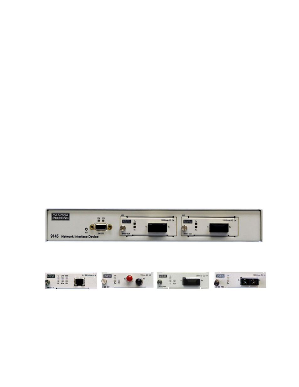
Power-Up and Front Panel Functions
The LEDs on the front panel show the system and port status. The STA and CFG LEDs
display management status. Interface Module has two, three or six LEDs, actual number is
dependant on Interface Module type.
Figure 11 – 9145 Front Panel
Figure 12 – UTP
10/100/1000 Mbps
Figure 13 – 10Mbps
Optical Module
Figure 14 – 100Mbps
Optical Module
Figure 15 – 1000Mbps
Optical Module
During power-up, all LEDs on the 9145 and Interface Modules light amber. When start-up
has complete, the LEDs on the 9145 display status is described in Table 1. Interface
Modules display status is described in Table 2.