Manual-5 rear panel description – Rane SR 3 User Manual
Page 5
Manual-5
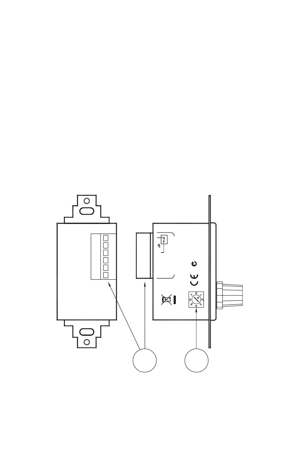
Rear Panel Description
1
Device Address switch
assigns the device its RW 485 address. Addresses 0
through 7 are valid.
2
6-wire Euroblock connector.
Connects the SR 3 to a controller. A con-
nects to RS-485 data +, B connects to RS-485 data –. +V is the positive
side of the power supply rail. –V is the negative/ground side of the power
supply rail. Ground is the connection point for the shield when shielded
cable is used. When the Encoder Lock pin is grounded and Auto Lock is
enabled, encoder input is ignored by the SR 3. This, for example, allows a
keyed switch to be installed next to the SR 3 that allows the device to be
“locked” so no one could change system volume.
1
2
ACN 001 345 48
2
RANE CORP
.
REMOTE INTERF
ACE
POR
T
MADE IN U.S.A
.
ADDRESS
AB
ENCODER LOCK
+V
-V
SR
3
- SRM 66 (8 pages)
- SRM 66 (10 pages)
- Serato Scratch Live (24 pages)
- AC 22 (1993 version) (13 pages)
- AC 22B (1998 version) (13 pages)
- AC 22B (2003 version) (14 pages)
- AC 23 (1993 version) (18 pages)
- AC 23B (1998 version) (18 pages)
- AC 23B (2003 version) (17 pages)
- AC 24 (10 pages)
- AD 13 (13 pages)
- AD 22 (4 pages)
- AD 22B (4 pages)
- AD 22D (6 pages)
- AP 13 (6 pages)
- AVA 22 1995 version (6 pages)
- AVA 22D 2000 version (6 pages)
- AVA 22D 2003 version (8 pages)
- AX 30 (2 pages)
- CM 86 (4 pages)
- CP 31 (4 pages)
- CP 52 1997 version (7 pages)
- CP 52 2003 version (8 pages)
- CP 62 (8 pages)
- CP 64 (1999-2004 version) (12 pages)
- CP 64 (2004-2006 version) (10 pages)
- CPR 1 (4 pages)
- DA 216 (1996 version) (4 pages)
- DA 216a (1999 version) (4 pages)
- DA 216a (2003 version) (6 pages)
- DA 26 (2001 version) (4 pages)
- DA 26 (2003 version) (6 pages)
- DC 22 (2003 version) (8 pages)
- DC 22S (2009 version) (8 pages)
- DC 24 Users Guide [RaneNote 130] (6 pages)
- DC 24 Manual (4 pages)
- DEQ 60 (6 pages)
- DH 1 (1 page)
- DH 1E (1 page)
- DMS 22 (4 pages)
- ECS Hardware (ECB 62e and ECM 82e) (14 pages)
- ECS v2 Hardware (ECB 6 and ECM 8) (14 pages)
- ECS RaneWare (32 pages)
- ECS v2 RaneWare (RaneWare 2.1) (33 pages)
- ECM 64 (26 pages)