Funktionsbeschreibung, Description du fonctionnement, Function description – Pilz PNOZ X5 12VDC 2n/o User Manual
Page 2
- 2 -
Das Schaltgerät erfüllt folgende Sicherheits-
anforderungen:
• Schaltung ist redundant mit Selbstüberwa-
chung aufgebaut
• Sicherheitseinrichtung bleibt auch bei Aus-
fall eines Bauteils wirksam.
• Bei jedem Ein-Aus-Zyklus der Maschine
wird automatisch überprüft, ob die Relais
der Sicherheitseinrichtung richtig öffnen und
schließen.
Funktionsbeschreibung
Das Schaltgerät dient dem sicherheits-
gerichteten Unterbrechen eines Sicher-
heitsstromkreises. Nach Anlegen der
Versorgungsspannung leuchtet die LED
"POWER". Das Gerät ist betriebsbereit, wenn
der Startkreis S33-S34 geschlossen ist.
• Eingangskreis geschlossen (z. B. Not-Halt-
Taster nicht betätigt):
Relais K1 und K2 gehen in Wirkstellung und
halten sich selbst. Die Statusanzeigen für
"CH.1" und "CH.2" leuchten. Die Sicher-
heitskontakte 13-14/23-24 sind geschlos-
sen.
• Eingangskreis wird geöffnet (z. B. Not-Halt-
Taster betätigt):
Relais K1 und K2 fallen in die Ruhestellung
zurück. Die Statusanzeige für "CH.1" und
"CH.2" erlischt. Die Sicherheitskontakte 13-
14/23-24 werden redundant geöffnet.
Description du fonctionnement
Le relais assure de façon sure, l’ouverture
d’un circuit de sécurité. A la mise sous
tension du relais (A1-A2), la LED "POWER"
s'allume. Le relais est activé si le circuit de
réarmement S33-S34 est fermé.
• Circuits d'entrée fermés (poussoir AU non
actionné) :
Les relais K1 et K2 passent en position
travail et s'auto-maintiennent. Les LEDs
"CH.1" et CH.2" s'allument. Les contacts
de sécurité (13-14/23-24) sont fermés.
• Circuits d'entrée ouverts (poussoir AU
actionné) :
Les relais K1 et K2 retombent. Les LEDs
"CH.1" et "CH.2" s'éteingnent. Les
contacts de sécurité (13-14/23-24)
s'ouvrent.
The relay complies with the following safety
requirements:
• The circuit is redundant with built-in self-
monitoring
• The safety function remains effective in the
case of a component failure.
• The correct opening and closing of the
safety function relays is tested
automatically in each on-off cycle.
Function Description
The relay provides a safety-oriented
interruption of a safety circuit. When the
operating voltage is supplied the LED
"POWER" is illuminated. The unit is ready
for operation, when the reset circuit S33-S34
is closed.
• Input circuit closed (e.g. the emergency
stop button is not pressed):
Relays K1and K2 energise and retain
themselves. The status indicators for
"CH.1" and "CH.2" illuminate. The safety
contacts (13-14/23-24) are closed.
• Input circuit is opened (e.g. emergency
stop button is operated)
Relays K1 and K2 de-energise. The
status indicators for "CH.1" and "CH.2" go
out. The safety contacts (13-14/23-24) will
be opened (redundant).
Modes de fonctionnement
• Commande par 1 canal : conforme aux
prescriptions de la EN 60204, pas de
redondance dans le circuit d’entrée. La
mise à la terre du circuit de réarmement
est détectée. En cas de mise à la terre des
circuits d'entrée, le fusible électronique
déclenche.
• Commande par 2 canaux: circuit d’entrée
redondant, la mise à la terre est détectée.
• Réarmement automatique : le relais est
activé dès la fermeture des canaux
d’entrée.
Betriebsarten:
• Einkanaliger Betrieb: Eingangsbeschaltung
nach VDE 0113 und EN 60204; keine
Redundanz im Eingangskreis; Erdschlüsse
im Startkreis werden erkannt. Bei
Erdschlüssen im Not-Halt-Kreis löst die
Sicherung der Versorgungsspannung aus.
• Zweikanaliger Betrieb: Redundanter Ein-
gangskreis, Erdschlüsse im Tasterkreis
werden erkannt.
• Automatischer Start: Gerät ist aktiv, sobald
Eingangskreis geschlossen ist.
Operating Modes
• Single-channel operation: Input wiring
according to VDE 0113 and EN 60204, no
redundancy in the input circuit. Earth faults
are detected in the reset circuit. Earth
faults in the emergency stop circuit trigger
the internal electronic fuse.
• Dual-channel operation: Redundancy in
the input circuit. Earth faults in the
emergency stop circuit are detected.
• Automatic reset: Unit is active as soon as
the input circuit is closed.
Le relais répond aux exigences suivantes :
• conception redondante avec auto-
surveillance
• sécurité garantie même en cas de
défaillance d’un composant
• test cyclique (ouverture/fermeture des
relais internes) à chaque cycle Marche/
Arrêt de la machine
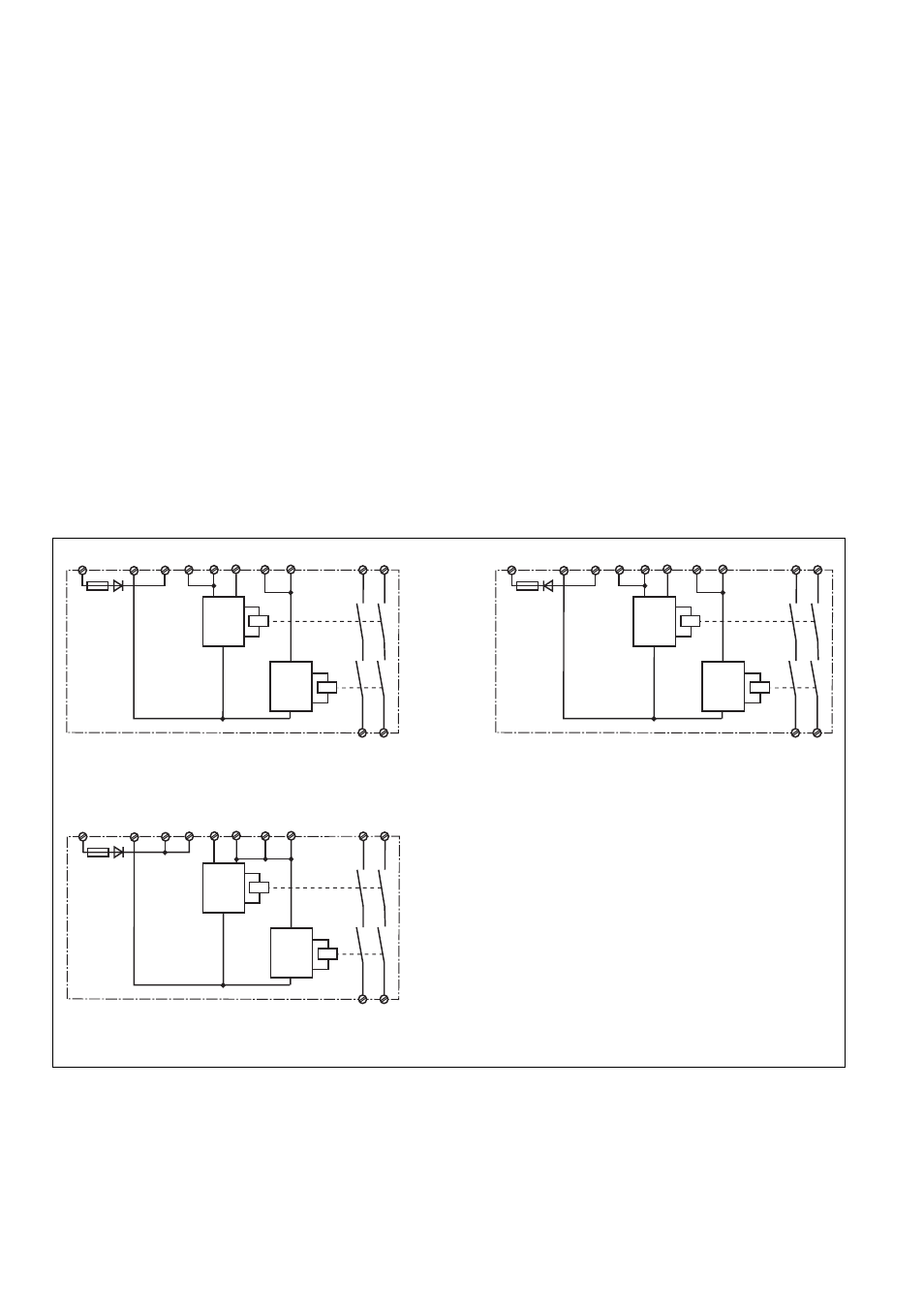
Fig. 1: PNOZ X5 Innenschaltbild/Internal Wiring
Diagram/Schéma de principe
A1 (L+)
A2 (L-)
S12
S33
S11
13
14
K1
K2
23
24
S34
Start
Unit
Start
Unit
S22
S12
U
B
A1 (L-)
A2 (L+)
S12
S33
S11
13
14
K1
K2
23
24
S34
Start
Unit
Start
Unit
S22
S12
U
B
Fig. 2: PNOZ X5J Innenschaltbild/Internal Wiring
Diagram/Schéma de principe
A1 (L+)
A2 (L-)
S12
S33
S11
13
14
K1
K2
23
24
S34
Start
Unit
Start
Unit
S22 S12
U
B
Fig. 3: PNOZ X5.1 Innenschaltbild/Internal Wiring
Diagram/Schéma de principe