Carrier 38AH044-084 User Manual
Page 9
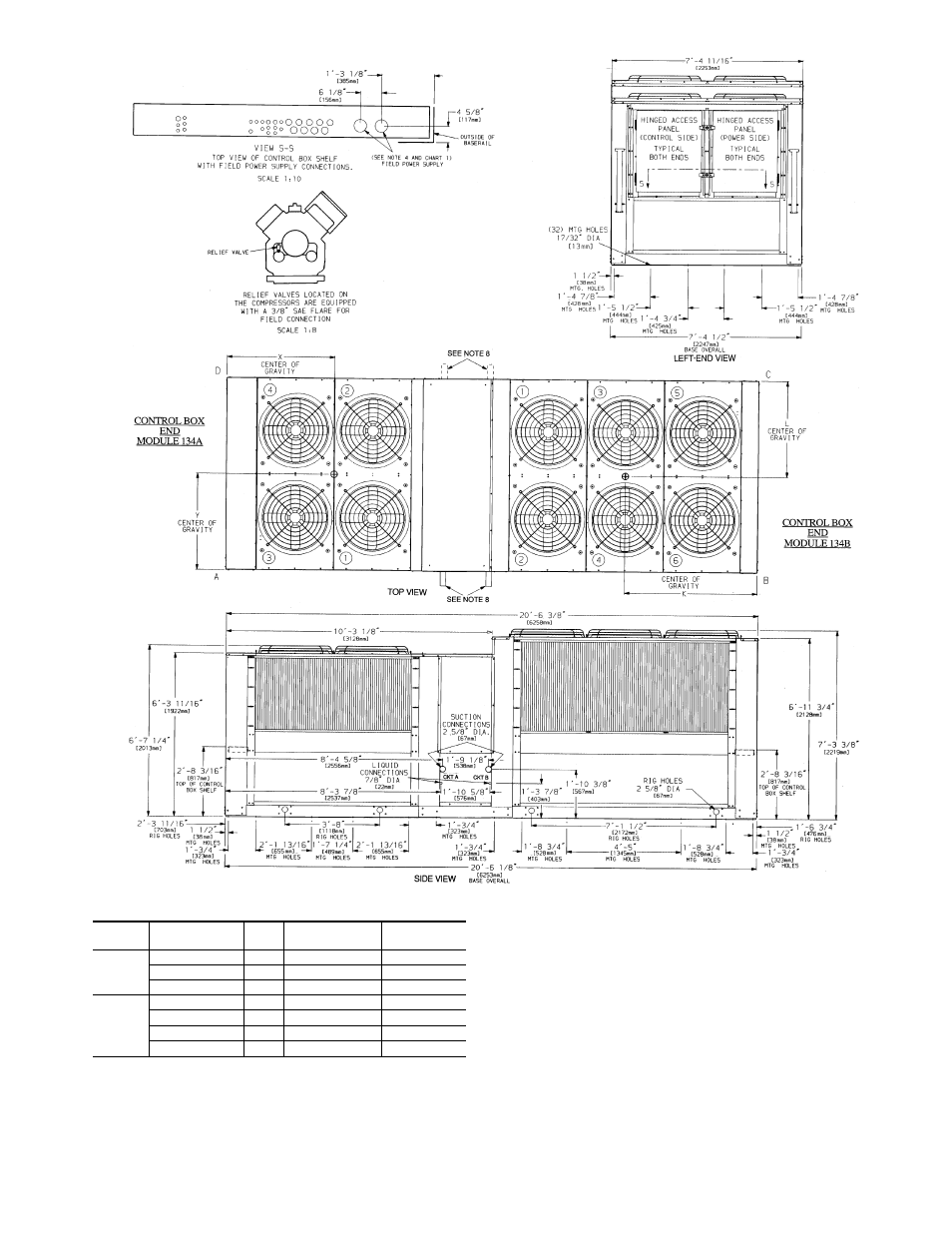
Chart 1, Field Power Supply Connections
UNIT
38AH
VOLTAGE
Hz
DIAMETER —
in. (mm)
QUANTITY
134A
208/230
60
3
5
⁄
8
(92)
1
460, 575, 380
60
2
1
⁄
2
(63)
1
346, 380/415
50
3
5
⁄
8
(92)
1
134B
208/230
60
2
1
⁄
2
(63)
2
460, 575
60
2
1
⁄
2
(63)
1
380
60
3
5
⁄
8
(92)
1
346, 380/415
50
3
5
⁄
8
(92)
1
LEGEND
C
— Copper Fin Coils
MTG — Mounting
SAE
— Society of Automotive Engineers
NOTES:
1. The approximate operating weight of the unit is:
38AH-134---
7507 lb (3405 kg)
38AH-134--C
8357 lb (3791 kg)
2. Unit must have clearances for airflow as follows:
Top — Do not restrict in any way.
Ends — 5 ft [1524 mm]
Sides — 6 ft [1829 mm]
3. Mounting holes may be used to mount unit to concrete pad. They are not
recommended for mounting unit to spring isolators.
4. One 3
5
⁄
8
Љ
(92-mm) dia hole is recommended for single-entry power into
Module 134A and 208/230-v units. Single entry power into Module 134B is
not recommended.
5. Circled numerals in Top View refer to condenser fans by position.
6. If spring isolators are used, a perimeter support channel between the as-
sembled unit and the isolators is recommended. Do not support each mod-
ule separately.
7. Each module of the unit must be rigged into position separately. The unit
must not be rigged after modules have been connected.
8. Suction and liquid connections can exit on either side of the unit.
9. Field power supply connections are required for each module.
10. See Table 1A or 1B for rigging center of gravity (Dimensions K,L,X,Y). See
Table 2A and 2B for A-D corner weights.
Fig. 6 — Dimensions — Unit 38AH134
9