Carrier 38AH044-084 User Manual
Page 26
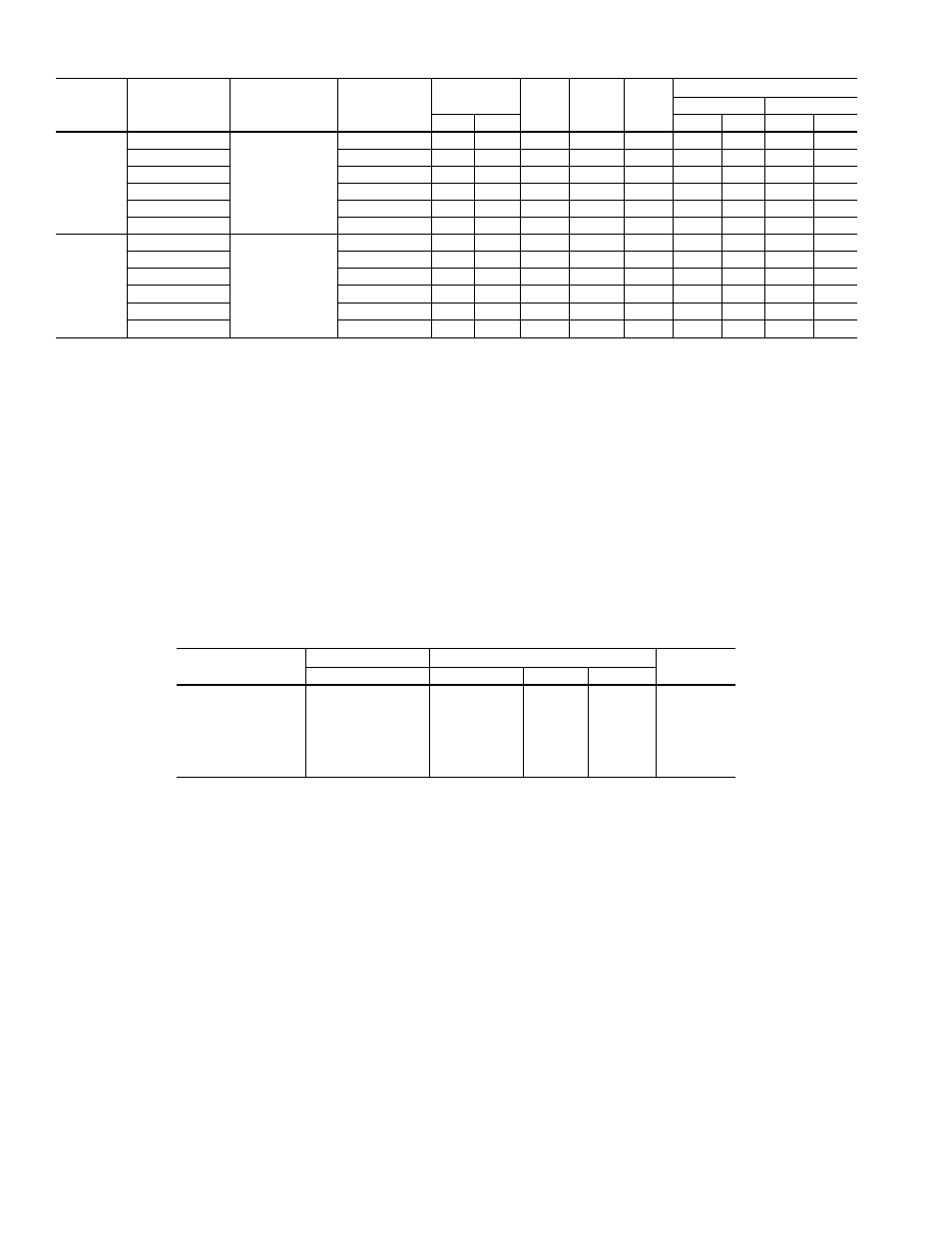
Table 12 — Electrical Data — 50/60 Hz (Units 38AH124, 134)
UNIT
38AH
MODULE
VOLTAGE
DESIGNATION
COMPRESSOR
A1/A2
MODEL NO.
NAMEPLATE
V-Ph-Hz
SUPPLY
VOLTAGE*
MCA
MOCP
ICF
COMPRESSOR†
A1
A2
Min
Max
RLA
LRA
RLA
LRA
124A
124B
134A
500
06E8275/
265
208/230-3-60
187
254
249.3
350
617.5
106.4
506
89.7
446
600
460-3-60
414
508
115.5
150
307.6
46.8
253
43.6
223
100
575-3-60
518
632
100.6
125
226.1
40.4
176
36.5
164
200
380-3-60
342
418
126.9
175
341.1
52.6
280
45.5
247
900
380/415-3-50
342
440
115.7
150
335.6
46.8
280
43.6
223
300 (PW)
346-3-50
325
367
129.8
175
230.5
53.8
168
44.9
148
134B
500
06E8299/
275
208/230-3-60
187
254
330.5
450
829.0
147.4
690
106.4
506
600
460-3-60
414
508
148.6
200
408.2
65.4
345
46.8
253
100
575-3-60
518
632
132.2
175
336.8
57.1
276
40.4
176
200
380-3-60
342
418
174.5
250
458.0
78.8
382
52.6
280
900
380/415-3-50
342
440
149.0
200
403.8
65.4
345
46.8
280
300 (PW)
346-3-50
325
367
170.8
250
300.4
79.5
229
53.8
168
LEGEND
FLA
— Full Load Amps
ICF
— Maximum Instantaneous Current Flow During Starting.
(The point in the starting sequence where the sum of
the LRA for the starting compressors, plus the total RLA
for all running compressors, plus the FLA for all running
fan motors is maximum.)
kcmil
— Thousand Circular Mils
LRA
— Locked Rotor Amps
MCA
— Minimum Circuit Amps (used for sizing; complies with
National Electrical Code [NEC] [U.S.A. Standard],
section 430-24).
MOCP — Maximum Overcurrent Protection (used for sizing
disconnect; complies with NEC [U.S.A. Standard],
section 440- 22).
PW
— Part Wind
RLA
— Rated Load Amps
*Units are suitable for use on electrical systems where voltage sup-
plied to unit terminals is within listed minimum to maximum limits.
†All compressors are across-the-line start only except 346-v, 3-ph,
50 Hz unit.
NOTES:
1. Maximum allowable phase imbalance: voltage - 2%; amps - 10%.
2. Maximum incoming wire size for terminal block is 500 kcmil.
Table 13 — Control Circuit Electrical Data — 50/60 Hz
UNIT
DESIGNATION
UNIT POWER
CONTROL POWER
AMPS
V-Ph-Hz
V-Ph-Hz
Min
Max
−500
208/230-3-60
115-1-60
103
127
4.1
−600
460-3-60
115-1-60
103
127
4.1
−100
575-3-60
115-1-60
103
127
4.1
−200
380-3-60
230-1-60
207
253
2.0
−800
230-3-50
230-1-50
207
253
2.0
−900
380/415-3-50
230-1-50
207
253
2.0
−300
346-3-50
200-1-50
180
220
2.4
NOTE: Units 38AH124 and 134 have 2 control boxes per unit, one in each module.
26