Carrier 38AH044-084 User Manual
Page 29
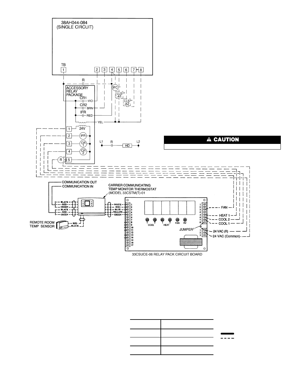
LEGEND
AWG
— American Wire Gage
CR
— Control Relay
HD
— Heating Device
IFC
— Indoor-Fan Contactor
IFR
— Indoor-Fan Relay
kcmil — Thousand Circular Mils
LLS
— Liquid Line Solenoid
NEC
— National Electrical Code
(U.S.A. Standard)
R
— Heating Relay (field-
supplied 24-v sealed coil,
10 va maximum rating)
RV
— Reversing Valve
TB
— Terminal Block
Factory Wiring
Field Wiring
*To control heating device and provide automatic indoor-
fan operation on heating.
†Jumper removed only when separate 24-v trans-
former power source is used to power the 33CSUCE-06
relay pack.
**Field-supplied.
NOTES:
1. Liquid line solenoid valves LLS-A1 and A2 are used
for solenoid drops.
2. Solenoid drop is a safety feature which prevents
refrigerant migration to the compressor during
the OFF cycle. It is recommended on all systems
and required on systems where piping exceeds
75 ft (22.9 m) in length.
3. The 33CSUCE-01 relay pack requires 10 va.
4. Factory wiring is in accordance with NEC; field modi-
fications or additions must be in compliance with
all applicable codes.
5. Wiring for field power supply must be rated 75 C
minimum. Use copper, copper-clad aluminum, or
aluminum conductors. Maximum incoming wire size
for each terminal block is 500 kcmil.
6. Terminal blocks are for external field control con-
nections. Control connections are to be Class 1
wiring.
7. Field-supplied components (IFC, LLS-A1, and
LLS-A2) must have a maximum sealed coil rating
of 30 va each (0.25 amp at 120 vac and 0.13 amp
Fig. 21 — Field Wiring, One 2-Stage Thermostat — 38AH044-084 Optional Single-Circuit Units
Internal 33CSUCE-06 relay contacts are rated for 1 amp/24 vac.
at 230 vac). Thermostats must have a minimum pilot
duty rating of 300 va (2.5 amps at 120 vac and
1.3 amps at 230 vac).
8. Replacement of factory wires must be with type
105 C wire or its equivalent.
9. Field-supplied liquid line solenoid valves installed at
the evaporator are required on all units.
10. Units have 175 va of power available for field-
installed accessories.
11. To minimize voltage drop, the following wire sizes are
recommended:
LENGTH —
Ft (M)
INSULATED WIRE — AWG
(35 C Minimum)
Up to 50
(15.2)
No. 18
50-75
(15.2-22.9)
No. 16
More Than 75
(22.9)
No. 14
29