Carrier 38AH044-084 User Manual
Page 4
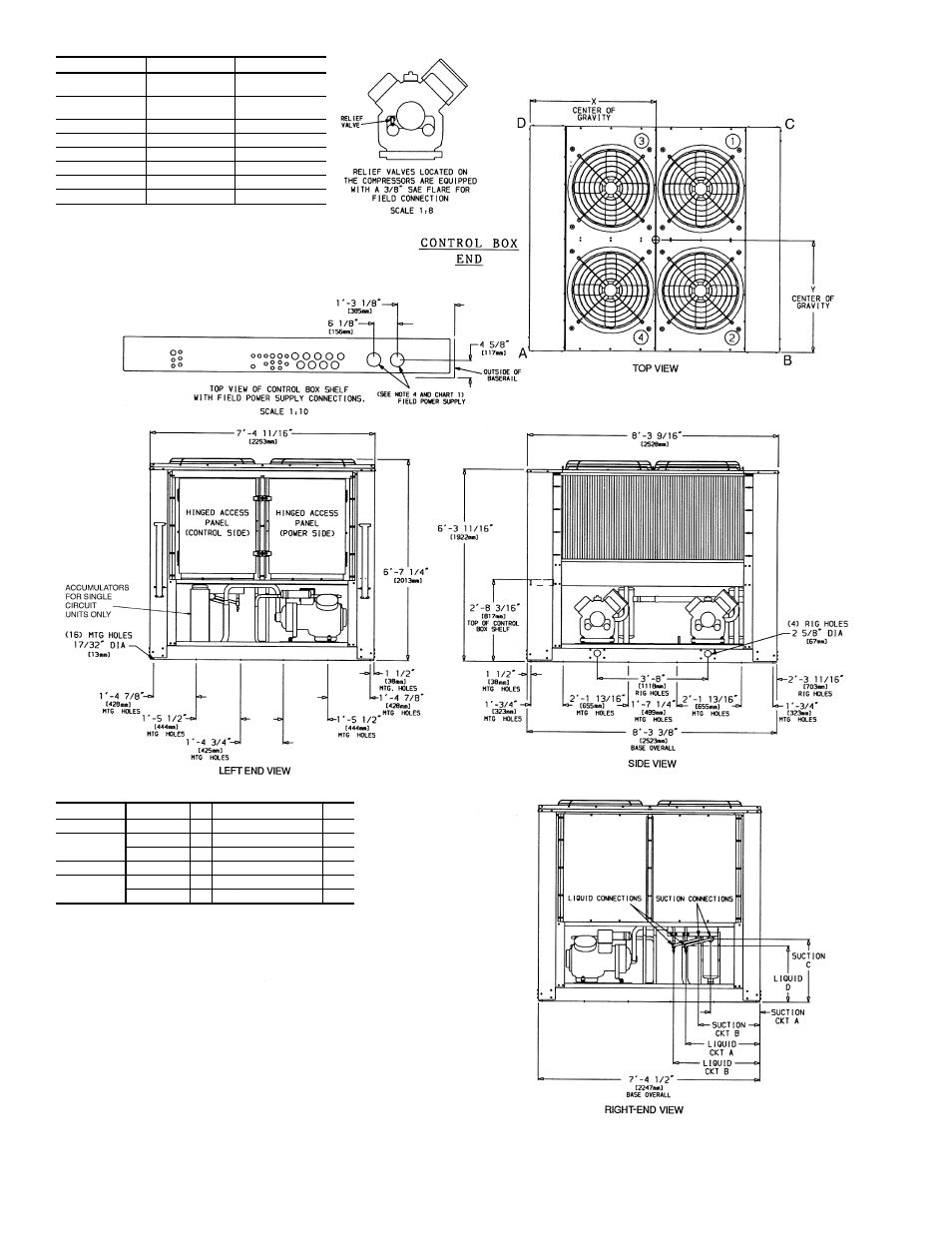
DUAL CKT
SINGLE CKT
SUCTION
CONNECTION(S)
2
1
⁄
8
Љ
Dia [54 mm]
2
5
⁄
8
Љ
Dia [67 mm]
LIQUID
CONNECTION(S)
7
⁄
8
Љ
Dia [22 mm]
1
1
⁄
8
Љ
Dia [29 mm]
SUCTION C
2
Ј
-
11
⁄
16
Љ
[627mm]
1
Ј
-10
5
⁄
16
Љ
[567mm]
LIQUID D
1
Ј
-10
1
⁄
16
Љ
[561mm]
1
Ј
-10
5
⁄
16
Љ
[567mm]
SUCTION (Ckt A)
1
Ј
-7
13
⁄
16
Љ
[503mm]
2
Ј
-
5
⁄
8
Љ
[626mm]
SUCTION (Ckt B)
2
Ј
-
5
⁄
8
Љ
[626mm]
—
LIQUID (Ckt A)
2
Ј
-5
3
⁄
4
Љ
[756mm]
2
Ј
-10
5
⁄
8
Љ
[879mm]
LIQUID (Ckt B)
2
Ј
-10
5
⁄
8
Љ
[879mm]
—
NOTES:
1. The approximate operating weight of the unit is:
38AH-044---
3259 lb [1478 kg]
38AH-044--C
3547 lb [1609 kg]
38AH-054---
3309 lb [1501 kg]
38AH-054--C
3597 lb [1632 kg]
38AH-064---
3565 lb [1617 kg]
38AH-064--C
3998 lb [1813 kg]
2. Unit must have clearances for airflow as follows:
Top — Do not restrict in any way.
Ends — 5 ft [1524 mm]
Sides — 6 ft [1829 mm]
3. Mounting holes may be used to mount unit to concrete pad. They are not recommended for mounting
unit to spring isolators. If spring isolators are used, a perimeter support channel between the unit and
the isolators is recommended.
4. One 3
5
⁄
8
Љ
(92 mm) diameter hole is recommended for single-entry power on size 064 (208/230-v) units.
5. See Table 1 for rigging center of gravity (Dimensions X,Y). See Table 2A and 2B for A-D corner weights.
6. Circled numerals in Top View refer to condenser fans by position.
Chart 1, Field Power Supply Connections
UNIT
VOLTAGE
Hz
DIAMETER — in. [mm]
QTY
044
230
50
3
5
⁄
8
[92]
1
044, 054
208/230
60
3
5
⁄
8
[92]
1
346, 380/415
50
2
1
⁄
2
[63]
1
044, 054, 064
460,575,380
60
2
1
⁄
2
[63]
1
064
208/230
60
2
1
⁄
2
[63]
2
346, 380/415
50
3
5
⁄
8
[92]
1
LEGEND
C
—
Copper Fin Coils
MTG
—
Mounting
SAE
—
Society of Automotive Engineers
Fig. 1 — Dimensions — Units 38AH044,054,064
4