Carrier 38AH044-084 User Manual
Page 49
Timer Functions —
(See Timer Cycle, Fig. 47.) Each
refrigeration circuit is controlled by an independent timer
which allows for the independent operation of each refrig-
eration circuit.
NOTE: Unit 38AH044-084 optional single-circuit units have
one timer which controls the lead compressor. Lag compres-
sor is controlled by CCPS (capacity control pressure switch).
SWITCH A — The timer is energized through contacts A-A1
or A-A2. This establishes the Time Guard
function which
prevents compressor short-cycling. Start of compressor is
delayed approximately 5.5 minutes after shutdown.
SWITCH B — The compressor is initially energized through
contacts B-B1.
SWITCH D — Contacts D-D1 provide a 2
1
⁄
2
-minute bypass
of the low-pressure switch at start-up for winter-start con-
trol. On 38AH044-084 optional single-circuit units, contacts
D-D2 control start-up of compressor A2.
SWITCH E — Contacts E-E1 provide a 40-second bypass
of the oil pressure switch at start-up. If oil pressure does not
build to the required minimum pressure in 40 seconds, the
compressor shuts down and the control circuit locks out.
On 38AH044-084 dual-circuit and 38AH094,104 units, lag
circuit B start-up is delayed 60 seconds after a call for cool-
ing is made to the circuit. This prevents compressor(s) in
both lead and lag circuits from starting at the same time.
Control Circuit Reset —
The control circuit locks out
if the unit shuts down because of low oil pressure, high
discharge gas temperature (DGT), or excessive high-side pres-
sure. To reset the control circuit, open and close the fan
circuit breaker (FCB). This resets the timer, and the unit
restarts under Time Guard control. At start-up, if the low-
pressure switch (LPS) does not close after 2
1
⁄
2
minutes, the
unit shuts down. When the pressure builds enough for the
LPS to cut in, the control circuit is energized automatically
and start-up proceeds under Time Guard control.
CONTROL
Sequence of Operation —
Units are controlled with
electromechanical components. Each refrigeration circuit
(except 38AH044-084 optional single-circuit units) is oper-
ated by an independent timer which controls the operation
sequence of each circuit.
On a call for cooling, first stage cooling thermostat TC1
closes. Condenser fans and timer (TM) are energized. After
approximately 7 seconds, timer contacts E-E1 close.
Approximately 12 seconds after TC1 closes, normally-open
timer contacts B-B1 close for 1 second. This energizes
compressor A1 contacts CA1 and starts the compressor. At
the same time, solenoid drop relays (SDRs) and liquid line
solenoid valve no. 1 (LLS-A for 38AH044-084 dual-circuit
units; LLS-A1 for all other units) open, and timer relay
no. 1 (TR2) is energized. Normally open TR2 contacts close,
completing a circuit around B-B1 and through compressor
A1 contactors to maintain compressor operation when B-B1
contacts open. Contacts E-E1 remain closed for approxi-
mately 40 seconds to bypass the oil pressure switch (OPS).
If oil pressure is insufficient when contacts E-E1 open, the
compressor stops, the timer cycles off, and the control cir-
cuit locks out. At start-up, timer contacts D-D1 are closed,
bypassing low-pressure relay contacts LPR-A for 2
1
⁄
2
min-
utes. This provides a winter start-up feature.
Approximately 2
1
⁄
2
minutes after TC1 closes, timer con-
tacts D-D1 open and D-D2 close. If pressure is insufficient
to close the low-pressure switch, the low-pressure switch
relay is open, the compressor shuts down, and the Time Guard
control is initiated. (Time Guard control prevents compres-
sor from restarting for 5 minutes after the demand for cool-
ing is satisfied.)
CONDENSER
COIL
FUSIBLE
PLUG
SUCTION
LINE
DISCHARGE
LINE
COMPRESSOR RAIL
ACCUMULATOR
Fig. 45 — Accumulator and Fusible Plug
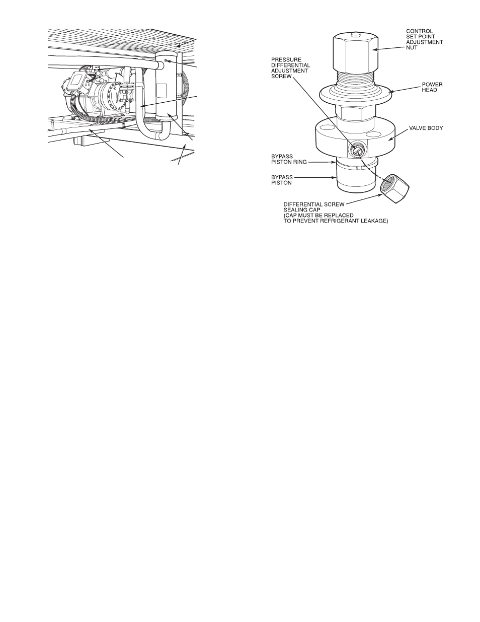
Fig. 46 — Pressure-Actuated Capacity Control Valve
49