Carrier 38AH044-084 User Manual
Page 18
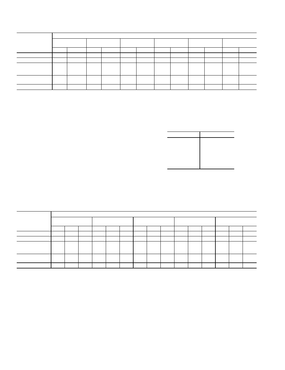
Table 8A — Refrigerant Piping Requirements for 38AH044-084
Optional Single-Circuit Units and 38AH124,134
Modular Units (Dual-Circuit) — 60 Hz
UNIT
38AH
TOTAL LINEAR LENGTH OF INTERCONNECTING PIPE — FT (M)
15-20
(4.6-6.1)
20-50
(6.1-15.2)
50-75
(15.2-22.9)
75-100
(22.9-30.5)
100-150
(30.5-45.7)
150-200
(45.7-61.0)
L
S
L
S
L
S
L
S
L
S
L
S
044
7
⁄
8
2
1
⁄
8
7
⁄
8
2
1
⁄
8
1
1
⁄
8
2
1
⁄
8
1
1
⁄
8
2
5
⁄
8
*
1
3
⁄
8
2
5
⁄
8
*
1
3
⁄
8
3
1
⁄
8
*
054
7
⁄
8
2
1
⁄
8
1
1
⁄
8
2
5
⁄
8
1
1
⁄
8
2
5
⁄
8
1
1
⁄
8
2
5
⁄
8
1
3
⁄
8
3
1
⁄
8
*
1
3
⁄
8
3
1
⁄
8
*
064;
Modules 124A,
124B,134A
1
1
⁄
8
2
1
⁄
8
1
1
⁄
8
2
5
⁄
8
†
1
1
⁄
8
2
5
⁄
8
†
1
3
⁄
8
3
1
⁄
8
*
1
3
⁄
8
3
1
⁄
8
*
1
3
⁄
8
3
1
⁄
8
*
074;
Module 134B
1
1
⁄
8
2
1
⁄
8
1
1
⁄
8
2
5
⁄
8
†
1
3
⁄
8
3
1
⁄
8
†
1
3
⁄
8
3
1
⁄
8
†
1
3
⁄
8
3
1
⁄
8
†
1
5
⁄
8
3
5
⁄
8
*
084
1
1
⁄
8
2
5
⁄
8
†
1
1
⁄
8
2
5
⁄
8
†
1
3
⁄
8
3
1
⁄
8
†
1
3
⁄
8
3
1
⁄
8
†
1
5
⁄
8
3
5
⁄
8
†
1
5
⁄
8
3
5
⁄
8
*
LEGEND
CV
— Constant Volume
L
— Liquid Line
S
— Suction Line
VAV — Variable Air Volume
*Double suction riser required on all units configurations if condens-
ing unit is elevated above evaporator.
†Double suction riser required on units with factory installed VAV op-
tion or CV units with additional field installed unloader on circuit A1
(lead) compressor if condensing unit is elevated above evaporator.
NOTES:
1. Addition of field-installed unloaders on A2 (lag) compressor is not
recommended.
2. Piping sizes are based on unit operation above 40 F (4.4 C) satu-
rated suction temperature (SST). When operating below 40 F
(4.4 C), refer to Carrier System Design Manual, E20-II
ா
piping
design program, or ASHRAE Handbook to select proper line sizes.
3. Pipe sizes are based on the total linear length shown for each
column, plus a 50% allowance for fittings.
4. Suction and liquid line sizing is based on pressure drop equivalent
to 2 F (1.1 C) at nominal rating conditions. Higher pressure drop
design criteria may allow selection of smaller pipe sizes, but at a
penalty of decreased system capacity and efficiency.
5. Double suction risers may be required if condensing unit is
elevated above the evaporator. See footnotes and double suction
riser table below.
6. Refer to Carrier System Design Manual, E20-II design program,
or ASHRAE Handbook for further information on selecting pipe
sizes for split systems.
7. All pipe sizes are OD inches. Equivalent sizes in millimeters
follow:
in.
mm
7
⁄
8
22.2
1
1
⁄
8
28.6
1
3
⁄
8
34.9
1
5
⁄
8
41.3
2
1
⁄
8
54.0
2
5
⁄
8
66.7
3
1
⁄
8
79.4
3
5
⁄
8
92.1
Table 8B — Refrigerant Piping Requirements for Double Suction Risers,
38AH044-084 Optional Single-Circuit Units and 38AH124,134
Modular Units (Dual-Circuit) — 60 Hz
UNIT
38AH
TOTAL LINEAR LENGTH OF INTERCONNECTING PIPE — FT
15-50
(4.6-15.2)
50-75
(15.2-22.9)
75-100
(22.9-30.5)
100-150
(30.5-45.7)
150-200
(45.7-61.0)
A
B
C
A
B
C
A
B
C
A
B
C
A
B
C
044
—
—
—
—
—
—
1
5
⁄
8
2
1
⁄
8
2
5
⁄
8
1
5
⁄
8
2
1
⁄
8
2
5
⁄
8
1
5
⁄
8
2
5
⁄
8
3
1
⁄
8
054
—
—
—
—
—
—
—
—
—
1
5
⁄
8
2
5
⁄
8
3
1
⁄
8
1
5
⁄
8
2
5
⁄
8
3
1
⁄
8
064
Modules 124A,
124B,134A
1
5
⁄
8
2
1
⁄
8
2
5
⁄
8
1
5
⁄
8
2
1
⁄
8
2
5
⁄
8
1
5
⁄
8
2
5
⁄
8
3
1
⁄
8
1
5
⁄
8
2
5
⁄
8
3
1
⁄
8
1
5
⁄
8
2
5
⁄
8
3
1
⁄
8
074;
Module 134B
1
5
⁄
8
2
1
⁄
8
2
5
⁄
8
1
5
⁄
8
2
5
⁄
8
3
1
⁄
8
1
5
⁄
8
2
5
⁄
8
3
1
⁄
8
1
5
⁄
8
2
5
⁄
8
3
1
⁄
8
2
1
⁄
8
3
1
⁄
8
3
5
⁄
8
084
1
5
⁄
8
2
1
⁄
8
2
5
⁄
8
1
5
⁄
8
2
5
⁄
8
3
1
⁄
8
1
5
⁄
8
2
5
⁄
8
3
1
⁄
8
2
1
⁄
8
3
1
⁄
8
3
5
⁄
8
2
1
⁄
8
3
1
⁄
8
3
5
⁄
8
LEGEND
—
— Not Required
Pipe A — Suction Riser Without Trap
Pipe B — Suction Riser With Trap
Pipe C — Suction Line to Condensing Unit
NOTES:
1. See Refrigerant Piping Requirements table at top of page to de-
termine need for double suction risers.
2. Pipe sizes are based on the total linear length, shown for each
column, plus a 50% allowance for fittings.
3. Suction and liquid line sizing is based on pressure drop equivalent
to 2 F (1.1 C) at nominal rating conditions. Higher design pressure
drop criteria may allow selection of smaller pipe sizes but at a pen-
alty of decreased system capacity and efficiency.
4. Refer to Carrier System Design Manual or to E20-II design
programs for further information on selecting pipe sizes for split
systems.
5. All pipe sizes are OD inches. See Table 8A notes for metric
equivalents.
6. Refer to Fig. 13 for double suction riser construction.
18