Welch Allyn Vital Signs Monitor - User Manual User Manual
Welch Allyn Equipment
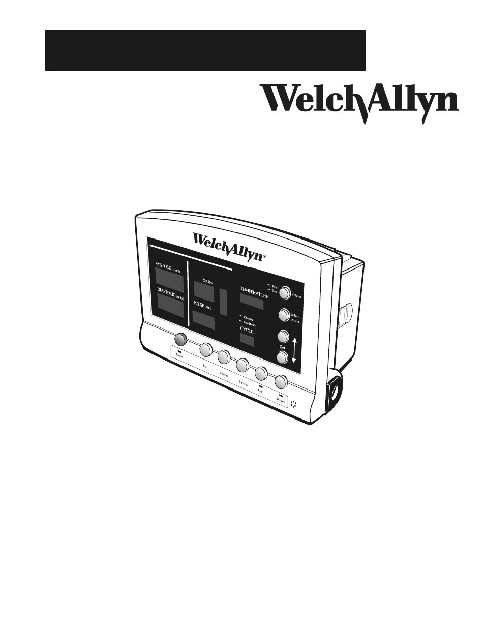
Table of contents
Document Outline
- About the Operator’s Manual
- Product Overview
- Indications/Contraindications for Use
- Safety Warnings & Cautions
- Special Features
- Blood Pressure Operating Modes
- Temperature Operating Modes
- SpO2 Operating Mode
- Pulse Rate Feature
- Front Panel Functions
- Side & Rear Panel Connections
- AC Power Connection
- Charging the Battery
- Power On/Off and System Check Procedure
- Setting the Date and Time
- 1. Initiate the Monitor's internal configuration settings menu by powering up the unit while the ...
- 2. Press the review button four (4) times to advance to the Date Set Screen. The year, month and ...
- 3. Use the SELECT ALARM button to select the date item to be changed. When selected, the date ite...
- 4. Use the SET buttons (arrow up or arrow down) to change the selected date item.
- 5. After making all the desired date changes, press the REVIEW button to save the changes and adv...
- 6. When in the Time Set Screen the hour (in 24 hour format) and minutes will appear in the systol...
- 7. When the time is set as desired, press the REVIEW button to save the time and advance to the n...
- 8. Press the POWER button to turn the Monitor off.
- Choosing Operating Modes
- Blood Pressure Hose & Cuff Connections
- Temperature Probe Connection
- SpO2 Sensor Connection
- Setting up the Printer
- 1. Grasp the printer cover as shown, and slide the cover off of the Monitor by sliding the cover ...
- 2. Holding a new roll of paper as shown, feed approximately 1 inch of paper into the slot at the ...
- 3. Press the paper "FEED" button to advance the paper 3 to 4 inches above the top paper slot.
- 4. Thread the paper through the paper slot on the printer cover. Slide the cover on to the Monito...
- Setting the Programmable Alarms
- Blood Pressure - High Systolic Limit
- Blood Pressure - Low Systolic Limit
- Blood Pressure - High Diastolic Limit
- Blood Pressure - Low Diastolic Limit
- Pulse Rate - High Limit
- Pulse Rate - Low Limit
- SpO2 - Low Limit
- Temperature Measurement Range Indicators
- Setting the DEFAULT Inflation Pressure Preset Level
- Blood Pressure Cuff Selection Criteria
- Positioning the Blood Pressure Cuff
- Manual Mode Blood Pressure
- 1. Ensure that the blood pressure cuff is properly sized and wrapped around the patient's upper a...
- 2. With the Monitor powered up, press the START button. The Monitor will inflate the cuff to the ...
- 3. The systolic display will show the pressure in the cuff as the blood pressure determination is...
- 4. When the measurement cycle is complete an audible tone will sound and the systolic, diastolic ...
- 5. The reading will be displayed for two minutes, and then this display will be blanked. The read...
- 6. Pressing CANCEL at any time during a blood pressure determination will cause the determination...
- Automatic Mode Blood Pressure
- 1. Ensure that the blood pressure cuff is properly sized and wrapped around the patient's upper a...
- 2. Press the AUTO button and note two dashes "--" in the CYCLE display. This is the default setti...
- 3. Select one of the ten pre-programmed cycle interval times by pressing the AUTO button until th...
- 4. When the desired interval is displayed, the operator may select the interval by pressing any o...
- 5. The unit will take its first automatic blood pressure determination 10 seconds after the time ...
- 6. For the first automatic blood pressure determination, the Monitor will inflate the cuff to the...
- 7. The systolic display will show the pressure in the cuff as the blood pressure determination is...
- 8. When the measurement cycle is complete an audible tone will sound and the systolic, diastolic ...
- 9. The measurement will be displayed until the next measurement cycle is initiated.
- 10. Pressing CANCEL at any time during a blood pressure determination will cause the determinatio...
- 11. To end an AUTO blood pressure session, press the AUTO button until two dashes "--" appear in ...
- Reviewing Information From Prior Cycles
- “Erase data” function
- Selecting the Temperature Scale
- 1. While the Monitor is turned off, press both the POWER and START buttons simultaneously. Hold t...
- 2. The operator can now cycle through the Monitor's internal configuration menu by pressing the R...
- 3. The first option illuminated on the TEMPERATURE display is "˚F." Pressing the ADJUST button tw...
- Selecting Temperature Operation Mode
- 1. While the Monitor is turned off, press both the POWER and START buttons simultaneously. Hold t...
- 2. The operator can now cycle through the Monitor's internal configuration menu by pressing the R...
- 3. Press the ADJUST button once to choose Monitor mode (˚F), or three times to choose Monitor mod...
- Taking An Oral Temperature
- 1. Ensure that the oral probe is connected to the unit. The oral probe has a BLUE tip. Accurate o...
- 2. Remove the probe from the probe holder. A short self-test mode will be initiated where every L...
- 3. Load a probe cover onto the probe by holding the probe collar with the thumb and forefinger, b...
- 4. Insert the probe tip gently into the patient's slightly opened mouth. Carefully slide the prob...
- 5. The probe should be held by the clinician during the entire temperature measurement process to...
- 6. During the temperature measurement cycle the TEMPERATURE display will show a series of LED seg...
- 7. When the final temperature has been reached a tone will sound and the temperature will be disp...
- 8. After the temperature measurement is complete, remove the probe from the patient's mouth and e...
- 9. Insert the probe into the probe holder before attempting to take another temperature measurement.
- 10. The current temperature is displayed for one minute after the probe is replaced in the holder...
- Taking an Axillary Temperature
- 1. Ensure that the oral probe is connected to the Monitor. The oral probe has a BLUE tip. Accurat...
- 2. Remove the probe from the probe holder. A short self-test mode will be initiated where every L...
- 3. Press the SET-Arrow Up button once. The display will now show “ALY” indicating that the Monito...
- 4. With the TEMPERATURE display showing “ALY”, load a probe cover onto the probe by holding the p...
- 5. Lift the patient’s arm so that the entire axilla is easily visualized. Place the probe as high...
- 6. Be sure that the probe tip will be completely surrounded by axillary tissue. Clothing or other...
- 7. Place the arm snugly at the patient’s side. Hold the arm in this position without movement of ...
- 8. In Normal Mode the Monitor will produce an audible tone and display the temperature reading wh...
- 9. After the temperature measurement is complete, remove the probe from the patient’s axilla and ...
- 10. Insert the probe into the probe holder before attempting to take another temperature measurem...
- Taking a Rectal Temperature
- 1. Ensure that the rectal probe is connected to the unit. The rectal probe has a RED tip. Accurat...
- 2. Remove the probe from the probe holder. A short self-test mode will be initiated where every L...
- 3. Load a probe cover onto the probe by holding the probe collar with the thumb and forefinger, b...
- 4. Separate the buttocks with one hand. Apply a thin coat of water-based lubricant when necessary...
- 5. Tilt the probe to ensure good tissue contact and continue to keep the buttocks separated while...
- 6. During the temperature measurement cycle, the TEMPERATURE display will show a series of LED se...
- 7. When the final temperature has been reached, a tone will sound and the temperature will be dis...
- 8. After the temperature measurement is complete, remove the probe from the patient's rectum and ...
- 9. Insert the probe into the probe holder before attempting to take another temperature measurement.
- 10. The current temperature is displayed for one minute after the probe is replaced in the holder...
- Measuring SpO2
- SpO2 Operation Mode
- Taking an SpO2 Measurement
- 1. Properly attach the appropriate sensor to the patient. Verify the cable to the sensor is attac...
- 2. The pulse signal bar graph will illuminate, indicating the relative strength and quality of th...
- 3. The SpO2% and pulse rate are updated approximately every second.
- 4. Removing the SpO2 sensor from the patient ends the monitoring period and immediately blanks th...
- Using the SpO2 Pulse Tone
- Printing Options: batch print or streaming print mode
- Error Indications and Interpretation
- General Guide to Problems and Corrective Actions
- Quick Guide to Taking a Manual (Auscultatory) Blood Pressure
- Cleaning
- Storage
- Battery Removal & Replacement
- 1. Ensure that the AC power transformer cord is disconnected from the Monitor, and that the Monit...
- 2. Use a Phillips-head screwdriver to remove the four (4) screws holding in the battery door. Rem...
- 3. Tip the Monitor and slide the battery out. Disconnect each of the 2 connectors and discard the...
- 4. Attach the battery connectors to the new battery as shown below.
- 5. Slide the new battery into the battery compartment as far as it will go.
- 6. Replace the battery door, tightening each of the (4) screws.
- 7. Connect the AC power transformer to the monitor and allow the new battery to charge for approx...
- 8. The battery is a non-spillable lead-acid battery. In the USA, call 1-800-SAV-LEAD for instruct...
- Calibration
- Blood Pressure Calibration Check
- 1. Put the Vital Signs Monitor into its blood pressure calibration check mode. In this mode, the ...
- 2. Connect the Vital Signs Monitor as shown. Make sure the pressure meter used to test the Vital ...
- 3. Pressurize the Vital Signs Monitor to slightly above 250 mmHg and bleed down the pressure no f...
- 4. Calculate the difference between the readings from the Vital Signs Monitor and the pressure me...
- Temperature Calibration Check
- 1. Turn the Monitor on by pressing the POWER button.
- 2. Remove the temperature probe completely from the holder and detach the connector, then insert ...
- 3. Insert, then remove the probe from the probe holder to reset the thermometer.
- 4. Wait for the temperture display test to be complete. Observe and record the temperture noted o...
- 5. The recorded temperature should be 97.3˚F ± 0.2˚F (36.3˚C +/- 0.1˚ C) if the Monitor is proper...
- SpO2 Calibration Check
- Service Policy
- Technical Assistance
- Service Manual/Spare Parts
- Service Loaners
- APPENDIX A: Mounting Accessories & Assembly Instructions
- Attaching the Monitor onto the Basket Assembly
- Removing the Monitor from the Mobile Stand
- Using the Wall Transformer Cord Wrap
- Attaching the Accessory Pack to the Basket
- Removing the Accessory Pack for the Basket
- Attaching and Removing the Accessory Pack from the Monitor
- Inserting the Box of Temperature Probe Covers
- 1. Lay BASE on floor with wheels down. Assemble POLE into BASE by inserting tapered end into hole...
- 2. Loosen HANDLE BRACKET screws (tool provided) and slide HANDLE over pole as shown. Position app...
- 3. Insert POLE CAP into the top of the POLE.
- 4. Assemble BASKET to BASKET plate by inserting (4) #8 x 3/16” long phillips screws through four ...
- 5. Assemble BASKET PLATE to POLE CAP using (1) #8 x 1/2” long phillips flat head screw inserted t...
- 6. Align two “C” holes in BASKET with corresponding holes in POLE and insert (2) #8 x 1/2 long ph...
- 7. Loosen HANDLE BRACKET screws again and slide HANDLE up under basket to desired height and loca...
- 8. For Model #5200-60 only, attach ACCESSORY PACK by orienting as shown in figure 1 and inserting...
- 1. Attach BASKET PLATE to wall by inserting (5) #8 flat head screws (not provided) through BASKET...
- 2. Assemble BASKET to BASKET PLATE by inserting (4) #8 x 3/16” long phillips screws through baske...
- 3. For Model #5200-62 only, attach ACCESSORY PACK by orienting as shown in figure 2 and inserting...
- 1. Attach BASKET PLATE to I.V. BRACKET by inserting (4) #8 x 1/4” long flat head phillips screws ...
- 2. Assemble BASKET to BASKET PLATE by inserting (4) #8 x 3/16” long phillips screws through baske...
- 3. For Model #5200-64 only, attach ACCESSORY PACK by orienting as shown in figure 2 and inserting...
- 1. Remove top two housing screws on one side of MONITOR only.
- 2. Orient BEDRAIL as shown and attach using (2) #4 x 1 1/8” long screws supplied. Securely tighte...
- 3. Repeat steps 1 & 2 on other side of MONITOR.
- 1. With monitor detached, assemble ANTI-THEFT BLOCK onto tab on BASKET PLATE oriented as shown be...
- 2. Attach monitor to BASKET PLATE.
- 3. Slide ANTI-THEFT BLOCK up until it seats against bottom of monitor. With allen wrench provided...
- 4. Retain allen wrench for future use.
- 1. Position PLATE in basket as shown.
- 2. Place TRANSFORMER in BRACKET. With transformer oriented as shown, secure bracket to plate usin...
- 3. Remove basket plate mounting screw indicated and replace with #8-32 x 1/2” long pan head phill...
- 4. Place STRAP over basket plate mounting screw in basket plate with hook and loop side towards b...
- APPENDIX B: Nurse Call Interface Wiring Diagram
- APPENDIX C: Supplies and Accessories
- APPENDIX D: Specifications
- APPENDIX A: Mounting Accessories & Assembly Instructions
- 95P517e.pdf
- Page 1
- Page 55.pdf