0 installation, 1 unpacking and assembly, 2 enclosure disassembly – Rice Lake IQ Plus 355 Installation Manual V1.17 User Manual
Page 8: 3 cable connections, Installation, Aution, 7arning
4
IQ plus 355 Installation Manual
2.0
Installation
This section describes procedures for connecting load
cells, digital inputs, and serial communications cables
to the IQ plus 355 indicator. Instructions for field
installation of the analog output option and
replacement of the CPU board are included, along
with assembly drawings and parts lists for the service
technician.
•
Use a wrist strap to ground yourself and protect
components from electrostatic discharge (ESD)
when working inside the indicator enclosure.
•
This unit uses double pole/neutral fusing which
could create an electric shock hazard. Procedures
requiring work inside the indicator must be
performed by qualified service personnel only.
•
The supply cord serves as the power disconnect for
the IQ plus 355. The power outlet supplying the
indicator must be installed near the unit and be
easily accessible
2.1
Unpacking and Assembly
Immediately after unpacking, visually inspect the IQ
plus 355 to ensure all components are included and
undamaged. The shipping carton should contain the
indicator with attached tilt stand, this manual, and a
parts kit. If any parts were damaged in shipment,
notify Rice Lake Weighing Systems and the shipper
immediately.
The parts kit contains the items listed below:
•
Capacity, identification, and annunciator
labels. Annunciator labels (PN 53374)
provide replacement overlay decals for
labeling primary and secondary units LEDs.
•
6-position screw terminal (PN 70599) for
connector J1 and a 7-position screw terminal
(PN 70600) for connector J4 (see Figure 2-3
•
Two 8-32NC x 7/16 fillister head screws (PN
30623). These screws occupy the holes below
and on either side of the setup screw on the
indicator backplate (see Figure 2-4 on
page 7).
•
Four 8-32NC x 3/8 machine screws (PN
14862) for the indicator backplate (see #24 in
•
Six neoprene washers (PN 45042) for
backplate screws included in the parts kit.
•
Four rubber bumpers (“feet”) for the tilt stand,
PN 42149.
•
Five cable ties, PN 15631.
•
Two ferrites (PN 66730), used to reduce
susceptibility to radiate electromagnet
interference and EMI installation instructions
(PN 67970).
•
Three each of grounding clamps (PN 67550),
external tooth lock washers (PN 15133), and
kep nuts (PN 14676) for cable shield
grounding against the backplate.
2.2
Enclosure Disassembly
The indicator enclosure must be opened to connect
cables for load cells, communications, digital inputs,
and analog output.
The IQ plus 355 has no on/off switch.
Before opening the unit, ensure the
power cord is disconnected from the
power outlet.
Ensure power to the indicator is disconnected, then
place the indicator face-down on an antistatic work
mat. Remove the screws that hold the backplate to the
enclosure body, then lift the backplate away from the
enclosure and set it aside.
2.3
Cable Connections
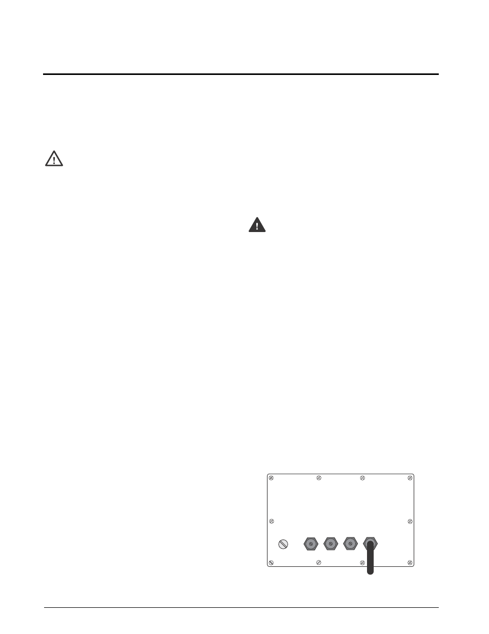
The IQ plus 355 provides four cord grips for cabling
into the indicator: one for the power cord, three to
accommodate load cell, communications, digital
inputs, and analog output cables. Two of the three free
cord grips come with a plug installed to prevent
moisture from entering the enclosure. Depending on
your application, remove the plug from any cord grip
that will be used and install cables as required.
NOTE:
Because the IQ plus 355 has no on/off switch,
the power cord serves as the power disconnect. The
power outlet must be located close enough to the
indicator to allow the operator to easily disconnect
power to the unit.
Figure 2-1 shows the recommended assignments for
the IQ plus 355 cord grips.
Figure 2-1. Recommended Cord Grip Assignments
#AUTION
7ARNING
"$1PXFS$PSE
-PBE$FMM$BCMF
4FSJBM$PNNVOJDBUJPOT
"OBMPH0VUQVU %JHJUBM*OQVU