2 load cells, 3 serial communications and digital inputs, Load cells – Rice Lake IQ Plus 355 Installation Manual V1.17 User Manual
Page 10: Serial communications and digital inputs
6
IQ plus 355 Installation Manual
2.3.2
Load Cells
To attach cable from a load cell or junction box,
remove connector J1 from the board. The connector
plugs into a header on the board as shown in
NOTE: Early versions of the IQ plus 355 CPU board used
a 7-pin load cell connector. The 7-pin connector is not
compatible with the current 6-pin header.
Wire the load cell cable from the load cell or junction
box to connector J1 as shown in Table 2-1. If using
6-wire load cell cable (with sense wires), remove
jumpers JP1 and JP2 before reinstalling connector J1
(see Figure 2-3). For 4-wire installation, leave
jumpers JP1 and JP2 on.
When connections are complete, reinstall connector J1
onto the header so that it snaps securely into place.
Use two cable ties to secure the load cell cable to the
inside of the enclosure.
Setting the Load Cell Compensation Jumper
The load cell compensation jumper (above the A/D
converter location on the CPU board; see Figure 2-3
on page 5) must be set ON for load cells with
unbalanced bridges. The compensation jumper has the
effect of lowering the positive excitation voltage.
Uncompensated unbalanced load cells can cause
instability or calibration errors.
For RL1040 and RL1042 load cells, set the
compensation jumper as follows:
• RL1040 load cells: jumper OFF
• RL1042 load cells: jumper ON
For other load cell types, use the following procedure
to determine the correct jumper position;
1. Disconnect load cell from indicator and use
an ohmmeter to measure the following:
• +EXC to +SIG, +EXC to –SIG
• –EXC to +SIG, –EXC to –SIG
Measured values between the excitation line
and each of the signal lines should be within
2–3
.
2. If the +EXC measurements are
5% larger
than the –EXC measurements, set the
compensation jumper in the ON position. If
the +EXC measurements are < 5% greater (or
are less) than the –EXC measurements, set the
jumper in the OFF position.
2.3.3
Serial Communications and Digital Inputs
To attach serial communications and digital input
cables, remove connector J4 from the board.
Connector J4 provides connections for the EDP
(Electronic Data Processing) port, printer port, and
two digital inputs. Connect communications and
digital input cables to connector J4 as shown in
Table 2-2.
Once cables are attached, reconnect J4 to the header
on the board (see Figure 2-6 on page 10). Use cable
ties to secure serial and digital input cables to the
inside of the enclosure.
The EDP port supports RS-232 communications only;
the printer port provides either active 20 mA output or
RS-232 transmission. Both ports are configured using
the SERIAL menu. See Section 3.0 on page 12 for
configuration information.
Digital inputs can be set to provide several indicator
functions, including all keypad functions. The inputs
are active (on) with low voltage (0 VDC) and can be
driven by TTL or 5V logic without additional
hardware. Use the DIG IN menu to configure the
digital inputs.
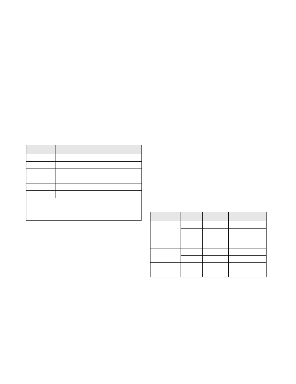
J1 Pin
Function
1
+SIG
2
–SIG
3
+SENSE
4
–SENSE
5
+EXC
6
–EXC
NOTES:
• Use grounding procedure described in Section 2.3.1
• For 6-wire connections, remove jumpers JP1 and JP2.
Table 2-1. J1 Pin Assignments
Port
J4 Pin
Label
Function
EDP Port
1
EDPT
RS-232 TxD
2
GND
RS-232 Ground /
–20 mA OUT
3
EDPR
RS-232 RxD
Printer Port
4
PRMA
+20 mA OUT
5
PRT
RS-232 TxD
Digital Inputs
6
IN2
Digital Input 2
7
IN1
Digital Input 1
Table 2-2. J4 Pin Assignments