4 analog output, 4 analog output module installation, 5 enclosure reassembly – Rice Lake IQ Plus 355 Installation Manual V1.17 User Manual
Page 11: 6 board removal, Analog output, Figure 2-4 on
Installation
7
2.3.4
Analog Output
If the optional analog output module is installed,
attach the output cable to connector J1 on the analog
output board. Table 2-3 lists the analog output pin
assignments.
Use the ALGOUT menu to configure and calibrate the
analog output module when cabling is complete. See
Section 2.4 for information about installing the analog
output module.
2.4
Analog Output Module Installation
To install or replace the analog output module, follow
the steps listed in Section 2.2 on page 4 for opening
the IQ plus 355 enclosure.
Mount the analog output module on its standoffs in
the location shown in Figure 2-3 on page 5 and plug
the module input into connector J5 on the IQ plus 355
board. Connect output cable to the analog output
module as shown in Table 2-3, then reassemble the
enclosure (Section 2.5).
See Section 7.8 on page 43 for analog output
calibration procedures.
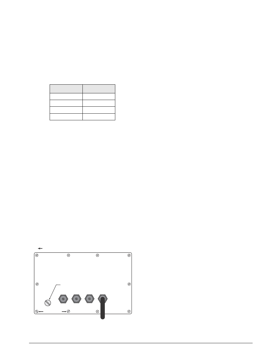
2.5
Enclosure Reassembly
Once cabling is complete, position the backplate over
the enclosure and reinstall the backplate screws. Use
the torque pattern shown in Figure 2-4 to prevent
distorting the backplate gasket. Torque screws to 15
in-lb (1.7 N-m).
Figure 2-4. IQ plus 355 Enclosure Backplate
2.6
Board Removal
If you must remove the IQ plus 355 CPU board, use
the following procedure:
1. Disconnect power to the indicator. Loosen
cord grips and remove backplate as described
2. Unplug connectors J1 (load cell cable), J4
(serial communications and digital inputs), J7
(keypad ribbon cable), and JP4 (setup switch).
Remove blue and brown power input wires at
JP7. If an analog output board is installed,
disconnect the analog output cable. See
Figure 2-3 on page 5 for connector locations.
3. Remove the four nuts from the corners of the
CPU board, then lift the board out of the
enclosure.
To replace the CPU board, reverse the above
procedure. Be sure to reinstall cable ties to secure all
cables inside the indicator enclosure.
Pin
Signal
1
+ Current Out
2
– Current Out
3
+ Voltage Out
4
– Voltage Out
Table 2-3. Analog Output Module Pin Assignments
4FUVQTXJUDIBDDFTTTDSFX
'JMMJTUFSIFBETDSFXT
5PSRVFCBDLQMBUFTDSFXTUPJOMC /N
5PSRVFQBUUFSO