Trimming procedure, Figure 2-9. potentiometer location, Figure 2-10. insert uni-strut closure strip – Rice Lake BCi Belt Scale - Installation & Operation Manual Version 2.00 User Manual
Page 25
BCi
Installation & Operation Manual - Integrator Hardware Installation
19
Trimming Procedure
Trimming is a process of equalizing the output from multiple individual load cells. If needed, load cell output can
be individually trimmed with potentiometers.
Whenever a substantial amount of trim (more than 5% of normal output), seems necessary to equalize output,
check for other possible problems. The best trim is always the least amount of trim. When all errors except cell
mismatch and cable extensions or reductions have been corrected, continue on with the trimming.
Use the following steps to properly trim the JB4SS junction box.
1. Determine the number of load cells needed.
2. Make sure jumpers are in place to enable trimming of the cells corresponding to each load cell. See
Figure 2-9 for the location of jumpers JP1, JP2, JP3 and JP4. Note that you will need to remove jumpers
for any unused cells.
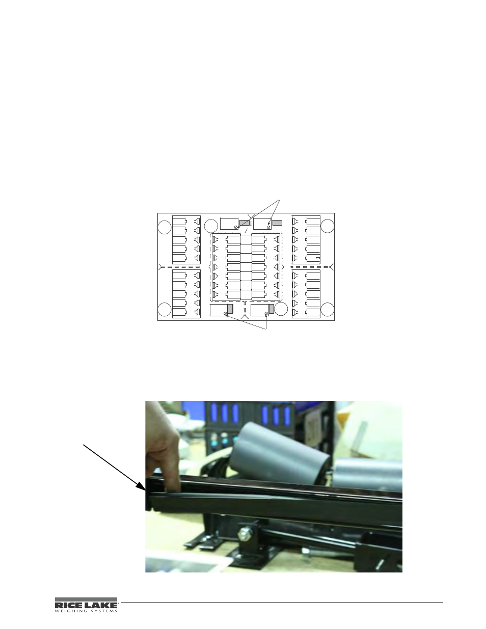
3. Set all potentiometers fully clockwise to give maximum signal output from each cell (see below for
location of potentiometers).
Figure 2-9. Potentiometer Location
Refer to the TuffSeal Installation manual (PN 91909) for additional information on the junction box.
Once all of the cables are attached and the scale carriage is completely assembled, take the uni-strut closure strip
and seal up the middle bars.
Figure 2-10. Insert Uni-strut Closure Strip
*0
*0
04
04
*0
04
%80
04
*0
#%,,
#%,,
#%,,
#%,,
).$
%8
3)
3($
3)
%8
-
2
.
)
3)
3#
)
!
'
%8
3)
3)
3($
%8
)
3
'
!
,
4
3)
-
3
)
.
,
4
2
%8
%8
3)
3($
3)
%8
3)
%8
3)
3($
%8
3($
3%
3%
%8
0OTENTIOMETERS
*UMPER
*0
3HADED
*UMPER
*0
3HADED
0OTENTIOMETERS
Insert Uni-strut
c l o s u re s t ri p
into uni-strut
center bars