0 integrator hardware installation, 1 unpacking and assembly, 2 scale carriage installation – Rice Lake BCi Belt Scale - Installation & Operation Manual Version 2.00 User Manual
Page 20: Integrator hardware installation
14
BCi
Installation & Operation Manual
2.0
Integrator Hardware Installation
This section describes procedures for assembling the scale carriage, adding the idlers to the scale carriage, speed
sensor connections, and any associated wiring.
Installation instructions for the integrator (BCi) are explained starting on page 25.
Take all necessary safety precautions when setting up the BCi In-motion belt scale system, including
wearing safety shoes, protective eye wear and using the proper tools.
2.1
Unpacking and Assembly
Upon receipt of the shipping pallet, visually inspect all components to make sure that they are included and
undamaged. The shipping carton should contain the scale carriage, the integrator, this manual, and a parts kit. If
any parts were damaged in shipment, notify Rice Lake Weighing Systems and the shipper immediately.
To ensure that all products received from the manufacturer are in good shape upon arrival, it is
recommended to fully inspect all contents and properly complete the bill of lading.
2.2
Scale Carriage Installation
The proper location must be chosen for installation of the scale carriage prior to installation. Information on page
12 helps choose the correct location for the scale carriage.
Once the correct location for the scale carriage is chosen, use the following steps to assemble the carriage as
there is minimal assembly required. Tools required for assembly include a 3/4" wrench and a small screwdriver
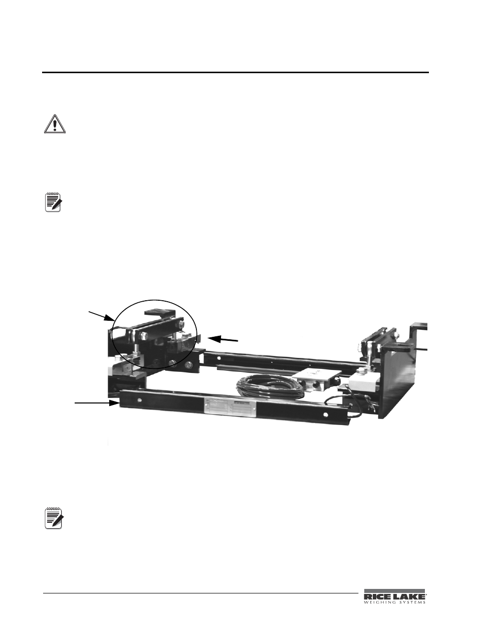
to work with the junction box. Figure 2-1 shows the component parts for the scale carriage that need to be
assembled.
Figure 2-1. Scale Carriage Component Parts
The exact steps for assembling the scale carriage may vary depending on the site location and size of carriage.
1. Space the two end plate assemblies far enough apart so that the uni-strut center bars will slide into the
channels on the end plate assembly making sure that the uni-strut center bar is centered equally from
both ends.
There should be roughly a 5/8
"
gap on each side and the drilled mounting holes (for junction box
placement), should be facing upwards.
Warning
Note
E n d p l a t e
assembly (x2)
Uni-Strut center
bars
Note