5 rs-422 communications, 6 20ma current loop, 4 fiber optics assembly – Rice Lake Intrinsically Safe User Manual
Page 66: Rs-422 communications, 20ma current loop
60
320IS Installation Manual
8.3.5
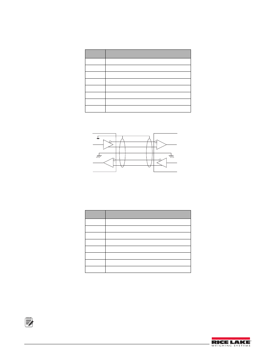
RS-422 Communications
To attach a PC or other device to the
320IS
’s RS-422 ports, select RS-422 standard in the indicator SERIAL menu
for the desired port (EDP and/or printer). EDP and printer ports should be configured separately. See Table 8-5
below for information on connecting RS-422 communications.
Figure 8-3. Typical RS-422 Wiring Paths
8.3.6
20mA Current Loop
To attach a PC or other device to the
320IS
’s 20mA ports, select current loop (CRLOOP) standard in the indicator
SERIAL menu for the desired port (EDP and/or printer). EDP and printer ports should be configured separately.
See Table 8-6 below for information on connecting 20mA current loop.
8.4
Fiber Optics Assembly
The
320IS
is equipped with duplex fiber optic ports for communicating with other devices located in the safe or
hazardous area. It provides electrical isolation and eliminates the use of I/O barriers commonly used in intrinsically
safe systems. The fiber optic wires are plastic; no polishing or further preparation is required. See Figure 8-1 on
page 58 for the location of the fiber optic ports on the
320IS
main board.
The fiber optic connections between the indicator and the
320IS
need to be cross-linked. The optical output
of the indicator should be attached to the input of the
320IS
, and the indicator’s input to the module’s output.
Pin
Description (Sign)
1
Signal Ground (GND)
2
—
3
—
4
—
5
RS-422 input (R+)
6
RS-422 input (R-)
7
RS-422 output (T+)
8
RS-422 output (T-)
Table 8-5. RS-422 Connections (CN2 and CN3)
Pin
Description (Sign)
1
Signal Ground (GND)
2
Isolated Ground (GNDx)
3
Receive Data (RCL) Passive
4
Transmit Data (TCL) Active
5
—
6
—
7
—
8
—
Table 8-6. 20mA Current Loop Connections (CN2 and CN3)
I/O Modul e
8
7
1
6
5
Note