5 load cells, Load cells – Rice Lake Intrinsically Safe User Manual
Page 20
14
320IS Installation Manual
9. Wire cable to connector CN3.
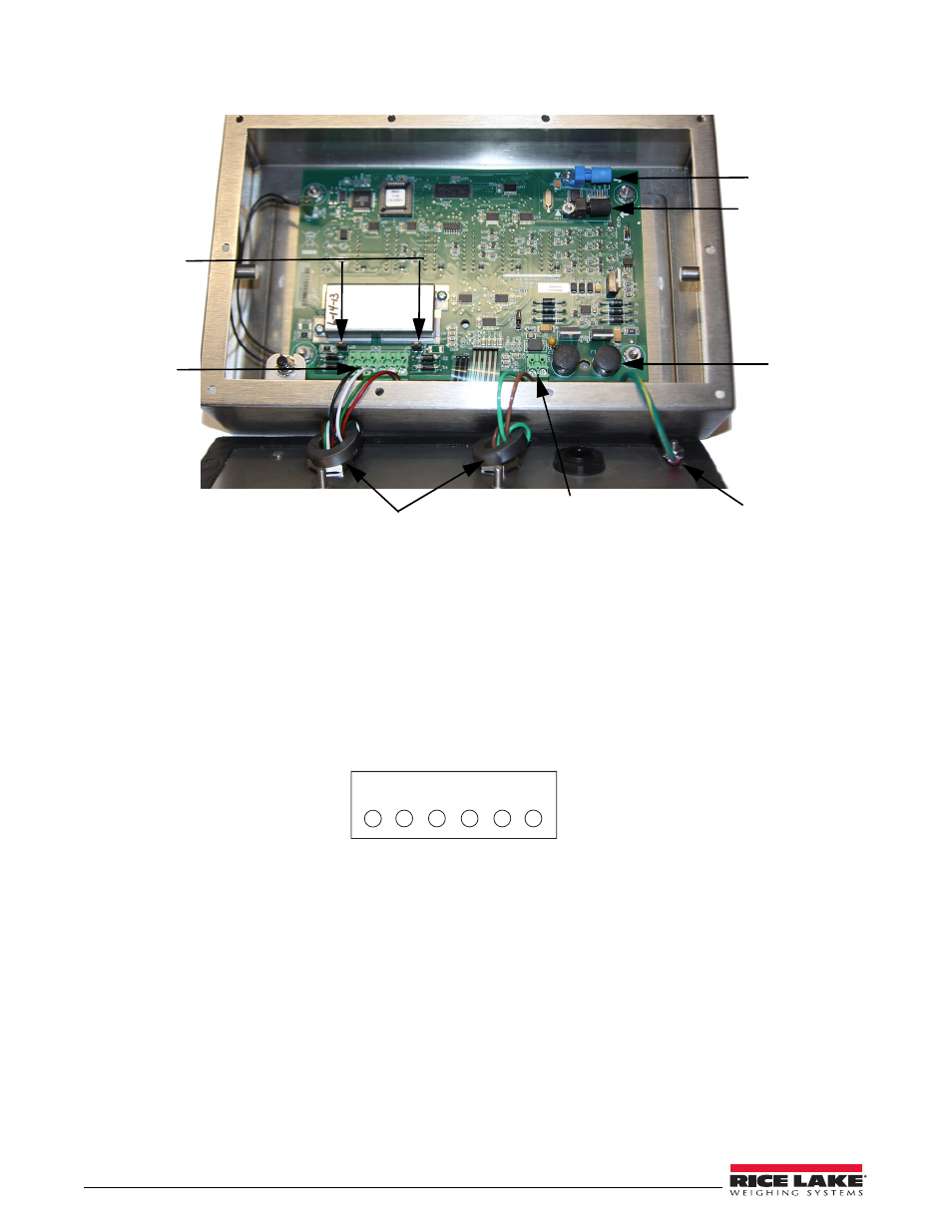
Figure 2-5. Cable Connections
2.4.5
Load Cells
To attach cable from a load cell or junction box, use six-position connector in parts kit. See Section 2.4 on page 10
for information on cabling through metal cord grips.
Wire the load cell cable from the load cell or junction box to connector CN3 as shown in Figure 2-6. If using 6-wire
load cell cable (with sense wires), remove jumpers J1 and J2 before installing connector CN3. For four-wire
installation, leave jumpers J1 and J2 on.
When connections are complete, reinstall connector CN3 on the board and use two cable ties to secure the load cell
cable to the inside of the enclosure.
Figure 2-6. CN3 Load Cell Connections
Load cell
connector
Power cable connector
Green = +Voltage
Brown = Return
125mA fully –
encapsulated
fuses
F1 & F2
Blue pptical
output
Black optical
input
Ferrite cores
C h a s s i s
ground
Sense jumpers
J1 & J2
1 2 3 4 5 6
CN3
-Excitation
-Sense
-Signal
+Signal
+Sense
+Excitation