5 analog outputs – Rice Lake Intrinsically Safe User Manual
Page 67
320IS Installation Manual - Appendix B
61
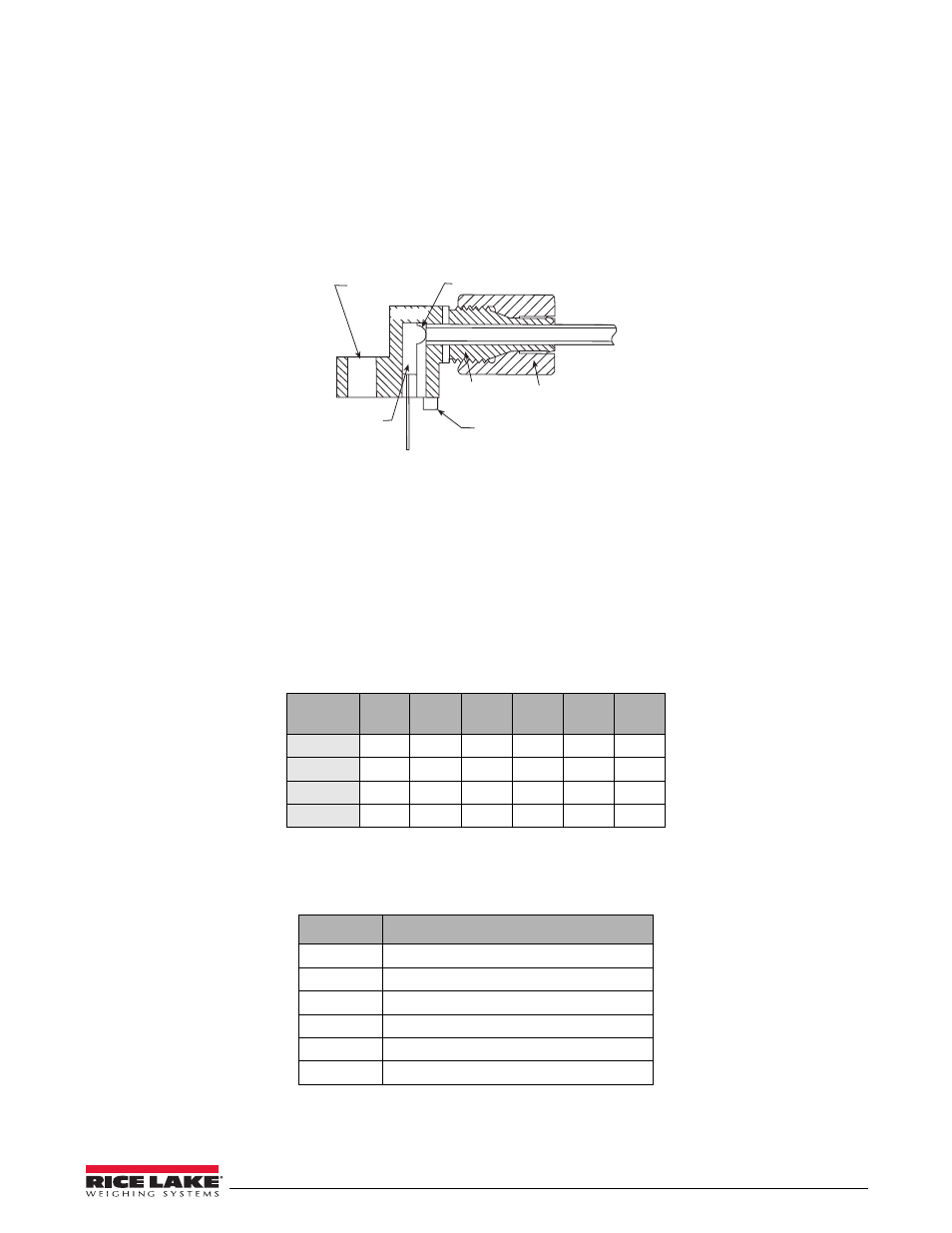
Use the following steps for assembling the fiber optics connectors of the
320IS
:
1. Cut off the ends of the fiber optic cable with a single-edge razor blade or sharp knife. Try to obtain a
precise 90º angle.
2. Insert the fiber through the locking nut and into the connector until the core tip seats against the internal
micro-lens.
3. Screw the connector locking nut down to a snug fit, locking the fiber in place.
4. Secure duplex fiber optic cable to wire tie mounting button located on I/O Module circuit board (see
Figure 8-1 on page 58) using wire ties included in parts kit.
Figure 8-4. Fiber Optics Connector
8.5
Analog Outputs
The
320IS
uses two 16-bit isolated analog output channels with 4-20mA and voltage (0-5V/±5V/0-10V/±10V)
outputs supplied from a DC/DC converter. The output voltage ranges are DIP-switch selectable (see Figure 8-1 on
page 58). Analog output configuration is done via setup mode in the indicator used with the
320IS
(see the
applicable indicator installation manual).
The analog output circuitry consists of two identical channels that can be assigned to gross or net weight values.
The analog outputs can be configured to operate as either current or voltage outputs. The voltage output range is
selected by configuring DIP switches SW1 (1-6) for channel 1 and SW2 (1-6) for channel 2 (see Figure 8-1 on
The analog output port is powered by an isolated DC-DC converter. The outputs available on connector CN1 are
listed in Table 8-8 below. See Figure 8-1 on page 58 for the location of CN1 and DIP switches.
Range
SW1-1
SW2-1
SW1-2
SW2-2
SW1-3
SW2-3
SW1-4
SW2-4
SW1-5
SW2-5
SW1-6
SW2-6
0–5V
OFF
OFF
OFF
ON
X
X
0–10V
OFF
ON
X
OFF
ON
X
±5V
ON
OFF
OFF
OFF
ON
X
±10V
ON
OFF
ON
OFF
OFF
ON
Table 8-7. Analog Output Range Configurations
Pin
Name
1
Ground (Analog Output 1 Common)
2
Analog Output 1 (current)
3
Analog Output 1 (voltage)
4
Analog Output 2 (current)
5
Analog Output 2 (voltage)
6
Ground (Analog Output 2 Common)
Table 8-8. CN1 Connectors
Optical Fiber
Locking Nut
Portioning Foot
Housing
Lens
Mounting Hole
Device
LED