0 appendix b, 1 unpacking and assembly, 2 enclosure disassembly – Rice Lake Intrinsically Safe User Manual
Page 63: 3 installation of the i/o module, Appendix b
320IS Installation Manual - Appendix B
57
8.0
Appendix B
This section describes procedures for connecting the analog and digital I/Os, fiber optic and serial communication
cables to the
320IS
.
Use a wrist strap to ground yourself and protect components from electrostatic discharge (ESD) when
working inside the indicator enclosure.
8.1
Unpacking and Assembly
Immediately after unpacking, visually inspect the
320IS
to ensure all components are included and undamaged.
The shipping carton should contain the
320IS
, Installation Manual (PN 78076), and a parts kit. If any parts were
damaged in shipment, notify Rice Lake Weighing Systems and the shipper immediately.
8.2
Enclosure Disassembly
The
320IS
enclosure must be opened to connect cables for load cells, communications, and power.
The I/O Module has does not have an on/off switch. Before opening the unit, ensure the power is
disconnected.
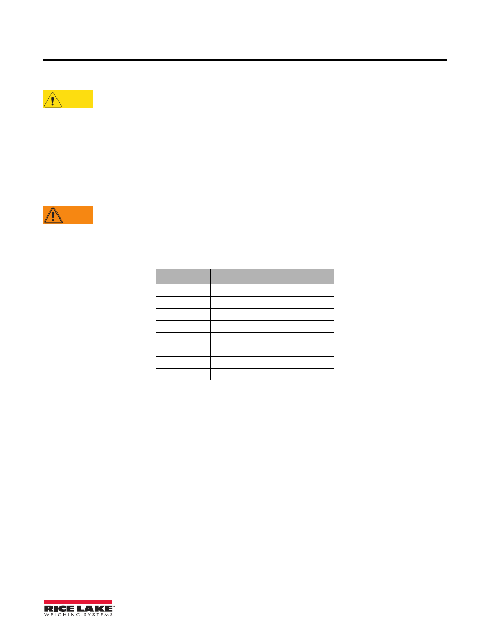
8.3
Installation of the I/O Module
The following section describes the wiring of various ports of the
320IS
. Table 8-1 below lists the connectors of the
main board of the
320IS
. See Figure 8-1 for port locations.
Connector
Description
CN1
Analog Outputs
CN2
EDP Port
CN3
Printer Port
CN4
Digital Inputs
CN5
Relay Outputs
CN8
DC Power
Optical Input
Light Port
Optical Output
Light Port
Table 8-1. I/O Module Wiring Ports
CAUTION
WARNING