3 load cell connections, Table 2-5. j15load cell connector, Figure 2-8. 6-wire load cell application – Rice Lake 120 Plus Digital Weight Indicator User Manual
Page 14: 4 optional i/o connections, 1 remote switcher, Table 2-6. remote switcher pin outs
10
120Plus Digital Weight Indicator Technical Manual
2.3
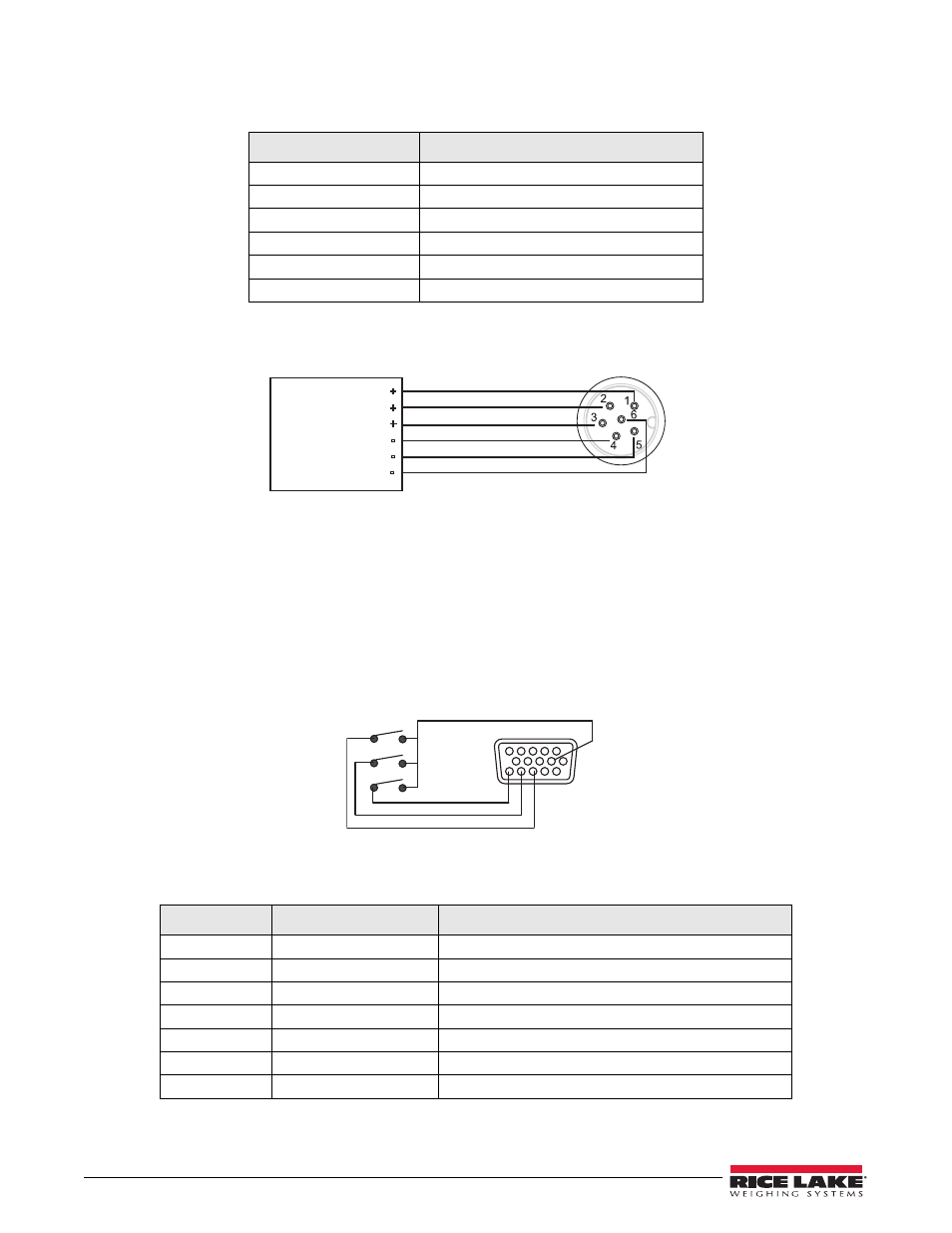
Load Cell Connections
The following table shows the load cell connection pins to the CPU.
6-Wire Load Cell Connection with Optional Quick Disconnect
Figure 2-8. 6-Wire Load Cell Application
2.4
Optional I/O Connections
The optional I/O board provides three digital inputs and two isolation digital relay outputs.
2.4.1
Remote Switcher
The 120 Plus indicator has provisions to connect an external input device such as a press switch (purchased
separately) to provide a keypad function. The keypad function can be set in the SETPNT menu; the external device
must provide a normally open (N.O.) momentary switch contact. The remote switch input requires a voltage free
contact between RSW input and GND.
Figure 2-9. Connect Remote Switcher Inputs to an External Input Device
The following table displays the pins and port functions of the female HDB15.
J1 Pin
Load Cell Connections on the CPU Board
1
- Excitation
2
- Sense
3
- Signal
4
+ Signal
5
+ Sense
6
+ Excitation
Table 2-5. J15Load Cell Connector
Pin
Port
Function
4
Out 1/2 Com
Setpoint 1 and 2 common
5
Out 2
Setpoint 2
7
RSW 1/2/3
Remote switcher 1, 2, and 3 ground
10
Out 1
Setpoint 1
13
RSW 1
Remote switcher 1
14
RSW 2
Remote switcher 2
15
RSW 3
Remote switcher 3
Table 2-6. Remote Switcher Pin Outs
Load Cell
SIGNAL
-
SENSE
-
SENSE
+
120 Plus
SIGNAL
+
EXITATION
+
EXCITATION
-
HDB15
7
15
14
13
RSW1
RSW2
RSW3
120 Plus