0 installation, Figure 2-1. 120 plus cable connections, 1 power connector – Rice Lake 120 Plus Digital Weight Indicator User Manual
Page 11: Power source, Earth, Power return, Table 2-1. power connection pin outs, 2 serial/print connector, Edp port, Edp txd
Installation
7
2.0
Installation
This section provides information for connecting the indicator to load cell digital inputs and outputs, and serial
communications cables. Battery installation is also described in this chapter in Section 2.5.
To power up the 120 Plus indicator, press the
ZERO
key on the front panel. The indicator must be installed near an
easily accessible power source or can be operated on an internal battery.
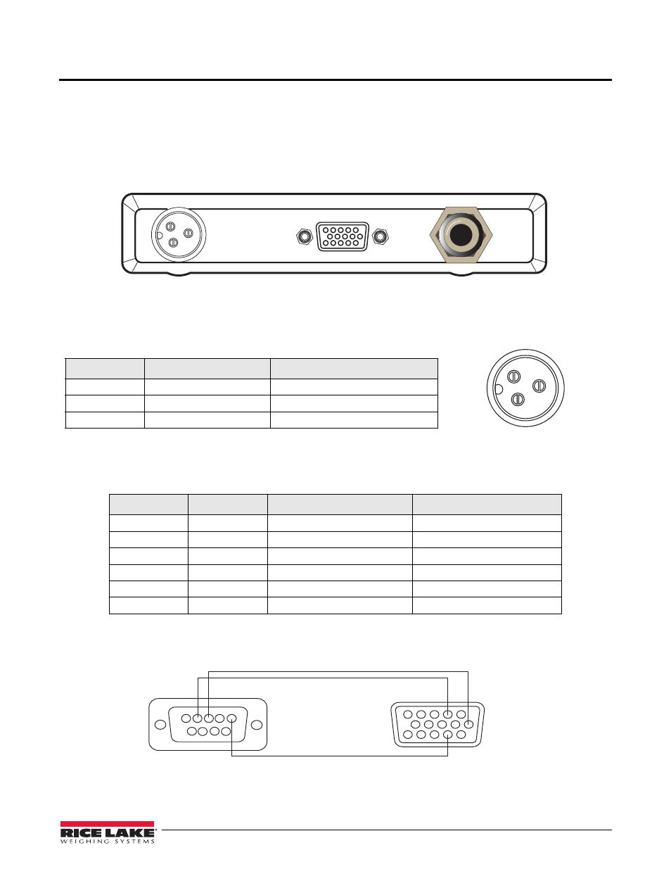
The various sockets on the 120 Plus are shown in Figure 2-1.
Figure 2-1. 120 Plus Cable Connections
2.1
Power Connector
The following table details the power connector pin functions.
2.2
Serial/Print Connector
Table 2-2 details the serial pin connector functions:
The RS-232 EDP port (RS-232C, may be connected to a PC, printer, or remote display) and the printer port (TxD
20 mA, may be connected to a PC, printer or remote display). Connections are shown in Figure 2-2.
Figure 2-2. Connect RS-232 EDP Port to PC
Pin
Designation
Function
1
DC+
Power Source
2
DC-
Power Source
3
Earth
Power Return
Table 2-1. Power Connection Pin Outs
Port
Pin
Designation
Function
EDP Port
2
EDP TxD
RS-232 Transmit Data
6
EDP RxD
RS-232 Receive Data
12
EDP GND
RS-232 Ground or -20 mA Out
Print Port
1
PR: TxD
RS-232 Transmit Data
11
PR: TxD 20 mA
+ 20 mA Out
12
PR: -20 mA OUT
RS-232 Ground or -20 mA Out
Table 2-2. Serial Connector
Load Cell
1
2
3
PC COM1
6
2
12
DB9-F
5
2 3
TxD
RxD
TxD
RxD
GND
HDB15
120 Plus