Figure 42, Following order as shown in – Kontron NSC2U IP Network Server User Manual
Page 60
NSC2U Server—Optional Component Installations
Kontron IP Network Server NSC2U
Product Guide, rev. 1.4
December 2009
60
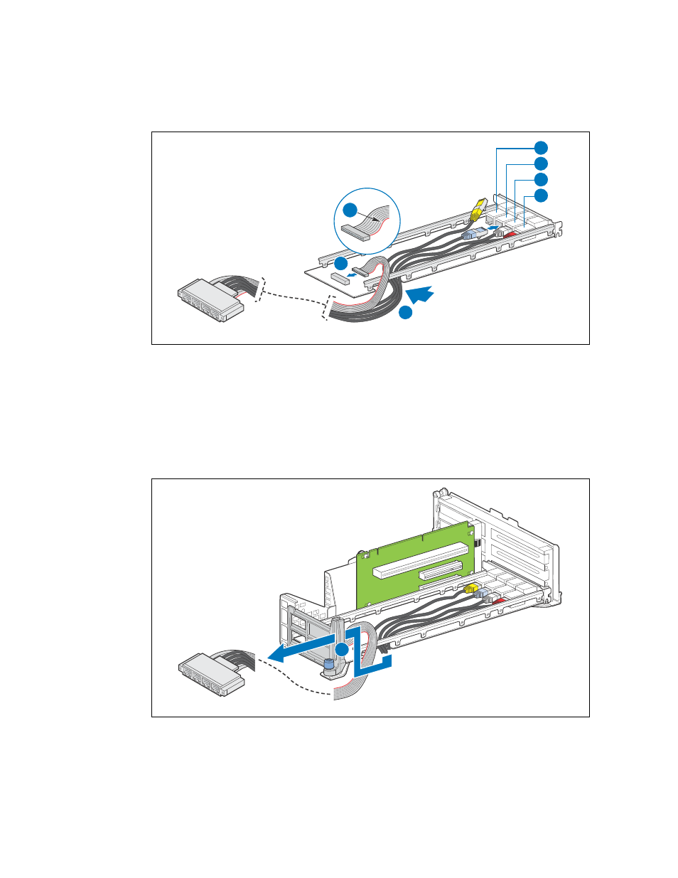
5. Route the end of the GbE cables going to the front panel through the retention clip.
(
, “A”)
6. Leave the LED ribbon cable out of the retention clip.
Note:
Do not fully re-install the riser card assembly in the chassis yet. The connection to the
front panel must be set up first. Put the assembly in position without inserting the riser
cards into the server board slots.
Figure 42.
Configuring the LAN Card
TS000319
G
D
E
C
B
F
A
Figure 43.
Routing the GbE Cables through the Retention Clip
TS000321
A