Board, Figure 40 – Kontron NSC2U IP Network Server User Manual
Page 58
NSC2U Server—Optional Component Installations
Kontron IP Network Server NSC2U
Product Guide, rev. 1.4
December 2009
58
4.5
Installing an RJ45 4xGbE LAN Card for Front Panel Access
The IP Network Server NSC2U supports 4xGbE LAN cards installed in the full-height
riser card slots with connections routed to the front panel.
Note:
The supported LAN card is the Intel®PRO/1000 AT Quad-Port Bypass Adapter.
The installation process consists of removing the chassis top cover and the processor
air duct, installing the LAN card into the riser card assembly as described in
“Installing or Replacing a PCI Add-in Card”
, replacing one of the front
panel filler panels with a 4xGbE escutcheon, and routing the LAN cables to the front
panel where the 1x4 connector is fastened to the escutcheon.
To route the cables to the front panel, the flex cable must be disconnected from the
SAS backplane board and the PCI fan assembly removed. (See
“Removing the PCI Fan Assembly” on page 102
.)
4.5.1
Installing the LAN Card into the Riser Card Assembly
1. Remove the riser card assembly from the chassis. For instructions, see
4.2.2, “Removing the PCI Riser Card Assembly” on page 53
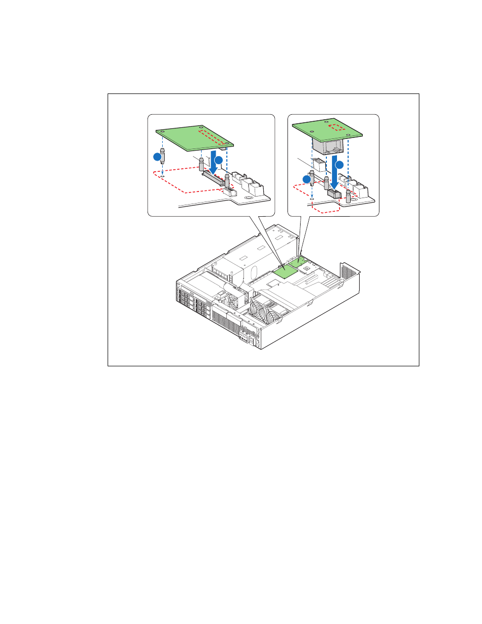
Figure 40.
Installing the Remote Management Module
TS000549
GCM3 Module
RMM Module
A
B
C
D