Mirrored mode memory configuration, Dimm sparing mode memory configuration, Single branch mode sparing – Kontron NSC2U IP Network Server User Manual
Page 40
NSC2U Server—Server Component Installations and Upgrades
Kontron IP Network Server NSC2U
Product Guide, rev. 1.4
December 2009
40
Functionally, DIMM slots A2 and B2 could also have been populated instead of DIMM
slots C1 and D1. However, the system will not achieve equivalent performance.
shows the supported DIMM configuration that is recommended because it
allows both memory branches from the MCH to operate independently and
simultaneously. FBD bandwidth is doubled when both branches operate in parallel.
3.4.2.6
Mirrored Mode Memory Configuration
When operating in mirrored mode, both branches operate in lock step. In mirrored
mode, branch 1 contains a replicate copy of the data in branch 0. The minimum DIMM
configuration to support memory mirroring is four DIMMs, populated as shown in
. All four DIMMs must be identical with respect to size, speed, and
organization.
To upgrade a four DIMM mirrored memory configuration, four additional DIMMs must
be added to the system. All four DIMMs in the second set must be identical to the first
with the exception of speed. The MCH will adjust to the lowest speed DIMM.
3.4.2.7
DIMM Sparing Mode Memory Configuration
The MCH provides DIMM sparing capabilities. Sparing is a RAS feature that involves
configuring a DIMM to be placed in reserve so it can be use to replace a DIMM that fails.
DIMM sparing occurs within a given bank of memory and is not supported across
branches.
There are two supported Memory Sparing configurations:
•
•
3.4.2.8
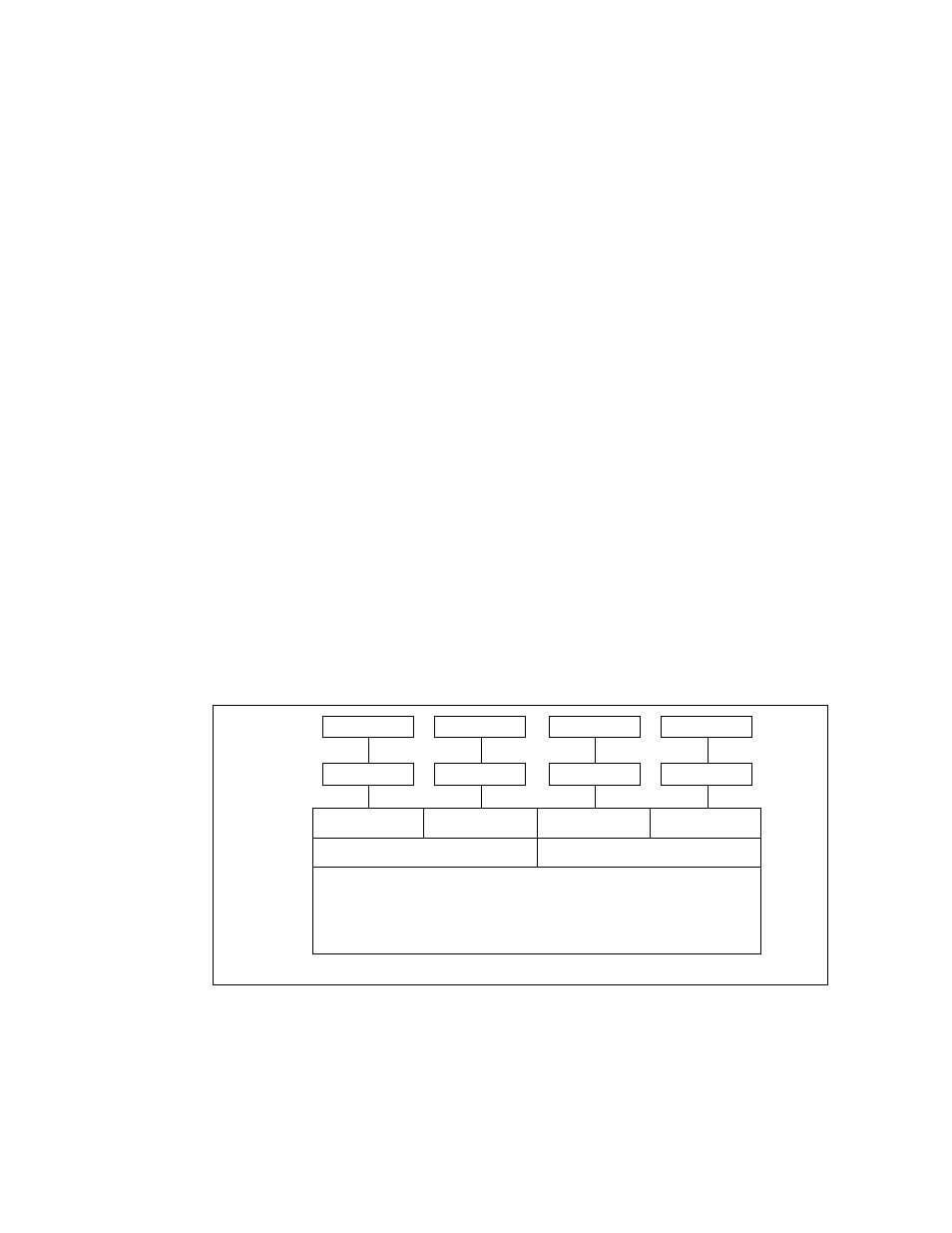
Single Branch Mode Sparing
shows the single branch memory sparing configuration.
The following rules apply:
• DIMM A1 and DIMM B1 must be identical in organization, size and speed.
• DIMM A2 and DIMM B2 must be identical in organization, size and speed.
Figure 23.
Single Branch Mode Sparing DIMM Configuration
TS000300
Channel A
Branch 0
Intel
®
5000P Memory Controller Hub
Channel B
DIMM A2
DIMM A1
DIMM B2
DIMM B1
Channel C
Branch 1
Channel D
DIMM C2
DIMM C1
Slot 2
Slot 1
DIMM D2
DIMM D1