Inserting the heat sink, Figure 32, Ac b – Kontron NSC2U IP Network Server User Manual
Page 47
Kontron IP Network Server NSC2U
December 2009
Product Guide, rev. 1.4
47
Server Component Installations and Upgrades—NSC2U Server
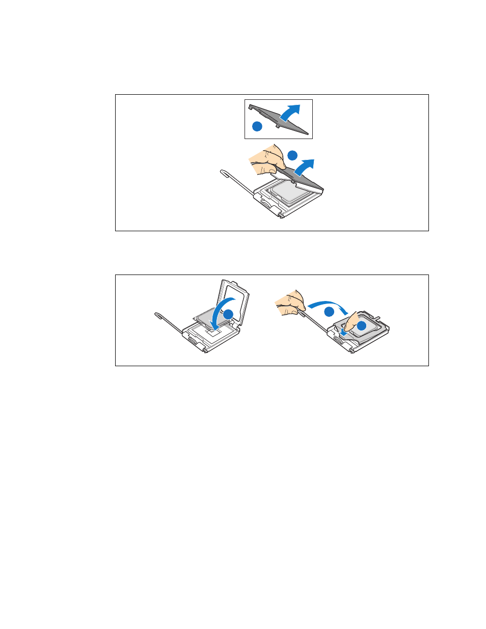
5. Close the load plate completely. (
, “A”)
6. Close the socket lever and ensure that the load plate tab engages under the socket
lever when fully closed. (“B” and “C”)
3.4.5.4
Inserting the Heat Sink
1. If this is a new heat sink (not the one you removed above), remove the protective
film, if present, on the Thermal Interface Material (TIM) located on the bottom of
the heat sink.
2. Set the heat sink over the processor, lining up the four captive screws with the four
posts surrounding the processor. Align the heat sink fins to the front and back of
the chassis for correct airflow (front to back). Use caution and make sure that
cables are not pinched beneath the heat sink. (See
.)
3. Loosely screw in the captive screws on the heat sink corners by tightening one,
then the one diagonally opposite, and so on.
4. Gradually and equally tighten each captive screw in diagonal order until each is
firmly tightened. See
for the order.
Caution:
The torque spec for these screws is 8 inch-pounds. Be careful not to exceed it.
Figure 31.
Removing the Socket Protective Cover
B
A
AF000772
Figure 32.
Closing the Processor Load Plate and Socket Lever
A
C
B
AF000773