Figure 5. nsc2u server front view (bezel removed) – Kontron NSC2U IP Network Server User Manual
Page 16
NSC2U Server—Features
Kontron IP Network Server NSC2U
Product Guide, rev. 1.4
December 2009
16
shows the front panel of the NSC2U Server with the bezel removed.
shows the NSC2U Server control panel.
Item
Description
Item
Description
A
Two slots for 4x GbE NIC ports (optional);
filler panels shown in illustration
B
Front panel control switches and status LEDs
(see
for details)
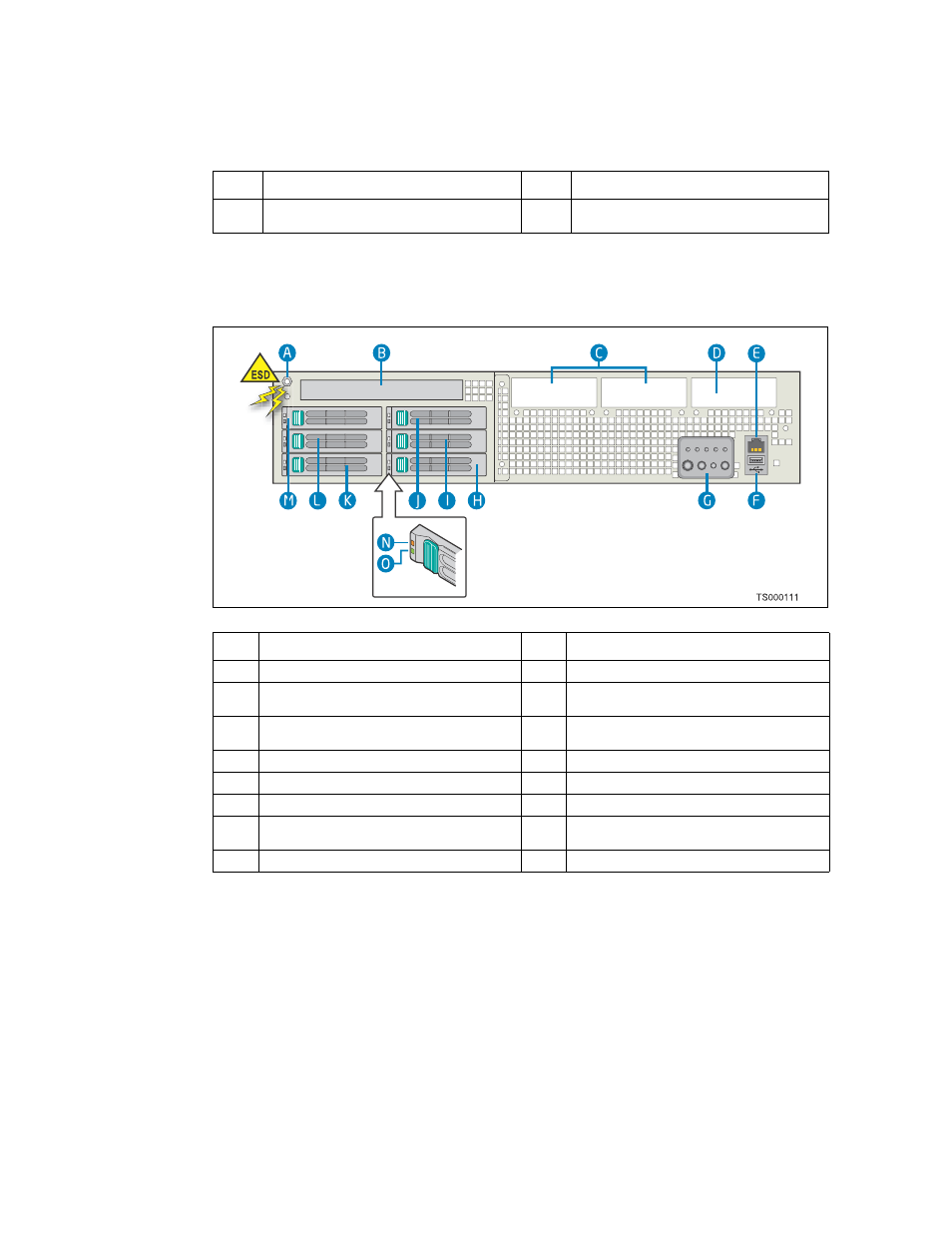
Figure 5.
NSC2U Server Front View (Bezel Removed)
Item
Description
Item
Description
A
Anti-static connection point
H
Hard drive bay 0
B
Optical drive (optional) or filler panel if no
drive is installed.
I
Hard drive bay 2
C
Two slots for 4x GbE NIC ports (optional);
filler panels shown in illustration
J
Hard drive bay 4
D
Optional slot for future design use
K
Hard drive bay 1
E
Front-panel serial port connector (RJ45)
L
Hard drive bay 3
F
USB port 2 connector
M
Hard drive bay 5
G
Front panel control switches and status LEDs
(see
for details)
N
Drive fault indicator (one per hard drive)
O
Drive activity indicator (one per hard drive)