5 sas front panel (sfp) board, 1 sfp board features, Sas front panel (sfp) board 2.5.1 – Kontron NSC2U IP Network Server User Manual
Page 18: Sfp board features, X/pcie add-in cards are given in, Table 2, N in, Table 3
NSC2U Server—Features
Kontron IP Network Server NSC2U
Product Guide, rev. 1.4
December 2009
18
The GbE NIC ports are intended to be installed with shielded cabling that is grounded at
both ends of the cable.
Warning:
The intra-building port(s) of the equipment or subassembly is suitable for connection to
intra-building or unexposed wiring or cabling only. The intra-building port(s) of the
equipment or subassembly MUST NOT be metallically connected to interfaces that
connect to the OSP or its wiring. These interfaces are designed for use as intra-building
interfaces only (Type 2 or Type 4 ports as described in GR-1089-CORE, Issue 4) and
require isolation from the exposed OSP cabling. The addition of Primary Protectors is
not sufficient protection in order to connect these interfaces metallically to OSP wiring.
2.5
SAS Front Panel (SFP) Board
The SAS Front Panel (SFP) board is located between the front panel and the two 80 mm
fans. The SAS drives connect into the SFP board for power and signals. The SFP board
also provides fan power connectors and the user interface for the system’s front panel.
2.5.1
SFP Board Features
The NSC2U Server SFP board has the following features:
• four switches to control power-on, reset, NMI, and the system ID
• one system status LED that indicates the presence of DC power in the system
• two system activity LEDs that indicate power-on and NIC activity
• one dual-color, hard drive LED that indicates activity/fault status for all internal SAS
drives
• one system ID LED that can be controlled remotely or by the system ID switch
• one RS-232 front panel port
• one USB2.0 front panel port
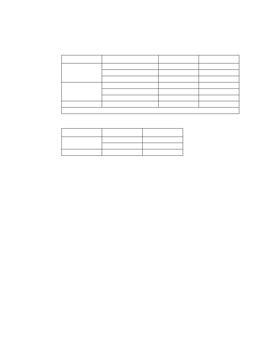
Table 2.
Full-Height Riser Card Configurations and Throughput
Configuration
Bottom Slot
Middle Slot
Top Slot
1 add-in card
PCI-X †
–
–
–
x8 or x4 PCIe
–
– –
x4
PCIe
2 add-in cards
PCI-X †
x8 or x4 PCIe
–
PCI-X †
–
x4 PCIe
–
x4 PCIe
x4 PCIe
3 add-in cards
PCI-X †
x4 PCIe
x4 PCIe
Note:
† Up to 133 MHz bus speed
Table 3.
Low-profile PCI Add-in Card Configurations and Throughput
Configuration
Lower Slot
Upper Slot
1 add-in card
x4 PCIe
x4 PCIe
2 add-in cards
x4 PCIe
x4 PCIe