Figure 37 – Kontron NSC2U IP Network Server User Manual
Page 56
NSC2U Server—Optional Component Installations
Kontron IP Network Server NSC2U
Product Guide, rev. 1.4
December 2009
56
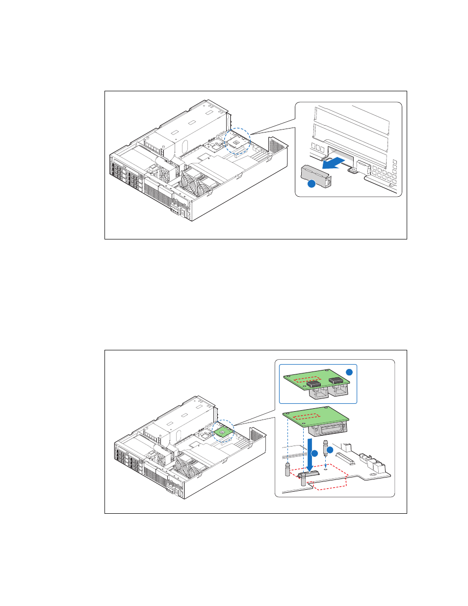
4. Snap the three I/O expansion module standoffs into the server board. (
,
“A”)
5. Attach the I/O expansion module to the server board connector (“B”) and the
standoffs.
6. If this is the last task you are performing, replace the riser card assembly, the
processor air duct and the top cover of the chassis. Reconnect all the external
devices and plug in the power cord(S).
For information about mounting the server in a rack, see
the Server into a Rack” on page 48
Figure 37.
Removing the I/O Module Filler Panel
TS000546
A
Figure 38.
Installing an I/O Expansion Module
TS000547
A
B
C